 Xark
XarkPDQ_GFX Library Development
The motivation for PDQ_GFX
A while ago, I noticed an article on Hackaday about how Paul Stoffregen (and crew) had optimized the Adafruit GFX SPI LCD driver for the Teensy 3.1 to achieve "warp speed" (see TFT LCDS HIT WARP SPEED WITH TEENSY 3.1). It was a nice demonstration of using advanced features of the 32-bit Teensy 3.1 micro-controller (along with code optimization). They used things like hardware /CS control and a hardware SPI FIFO to really speed things up from the generic Arduino API version (even when recompiled for the faster Teensy 3.1). Previously I had purchased an Adafruit SPI LCD breakout board that used this same controller and found it to be disappointingly slow (my AVR LCD gaming dreams were mostly dashed, and I didn't do much with it). At the time I just chalked it up to the fact that 8-bit AVR just wasn't up to the task of LCD graphics (especially over a slow-ish SPI bus). After seeing the impressive gain that the Teensy 3.1 was able to get, I decided it would be interesting to see if I could perhaps significantly speed up the library for Arduino AVR users without any "fancy 32-bit hardware". [Even though I have a Teensy 3.1 and they are great, I like an optimization challenge. :-) ]
In this write-up I hoped it might be interesting for me to go over some of the things I did to get about a 2.5 to 12 times times speedup (depending on primitive) using the same hardware. I did the bulk of this project many months ago, but am only now getting around to documenting it (so hopefully I am not too fuzzy on the details).
A look at the AVR SPI hardware in action
Since I had read about Paul's experience I had some ideas about what I could improve on the 8-bit AVR (however many of those optimizations were excluded as they used hardware capabilities that the AVR lacks). But the first thing to do was to take a look for myself. To start, I used my logic analyzer (Open Workbench Logic Sniffer) to see how the IL9341 driver was operating the SPI bus (a logic analyzer is a super handy and cost effective tool - I use mine to debug and explore digital hardware all the time).
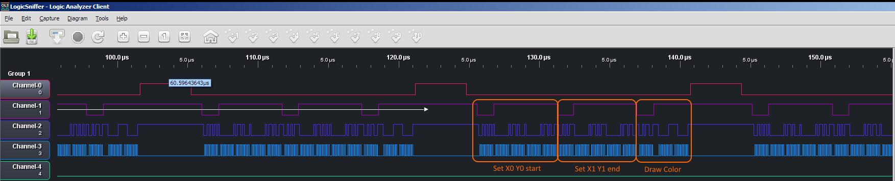
In the "before" logic analyzer capture picture, you can see part of a "drawPixel" command being sent from the AVR 328P to the LCD controller over the SPI bus. In case you aren't familiar with SPI or logic analyzer captures, the important thing to notice here is "channel-3". This is the SPI clock signal (called SCK). It goes high and then low once for every bit transfered over the SPI bus. The Adafruit library normally uses the AVR hardware SPI channel, as it is in this case (it can also "bit-bang" SPI, but that is much slower). They "crank up" the SPI speed to the maximum supported by a 16MHz AVR, which is 8MHz (this means one bit can be transferred every two AVR clock cycles). So the "blue chunks" on channel-3 represent 8-bits getting sent over the SPI bus (or one byte). Now, this is the "fastest" speed that the AVR can possibly send data over SPI (I believe the LCD SPI controller can go a maximum of ~25MHz and some micro-controllers and devices support 100MHz SPI or more, for comparison). However, while the bytes are clocked out at the maximum (fixed) speed, you can see there is a lot of "dead time" between each byte that could in theory be used to speed things up. Another thing I noticed is that the Adafruit library toggles the /CS signal on channel-0 almost every single byte sent. The /CS signal is "chip-select", when it is low the LCD will listen to the SPI bus (that "/" means active-low signal), when it is high it will ignore the bus so it can be shared with another device). Since we are going to be sending a whole bunch of commands all to the LCD, it seemed to me we can just pull /CS low once, do a bunch of commands (until we are going to return to the calling sketch) and then restore /CS back to high once (in case the SPI bus will be used to talk to another device, like the SD card that is on many of these LCD modules).
A peek under the covers of the software
I also did some examination of the "actual code" that runs for the library. To do this I needed to disassemble the code. Everything you need to do this is included in the IDE (which includes a complete "GNU toolchain" for AVR). I first enabled the "verbose compilation" option in the Arduino IDE and compiled an Adafruit GFX benchmark sketch. Then I opened a command prompt (I am using Windows, but this is much the same on Linux or OS X) and "cd"'d to the temporary folder the IDE was using (cut and paste is handy here, and you may also need to add double quotes if there is a space in any paths - Windows users may need to "reverse" slashes too). Then I cut and pasted the path the IDE was using for the toolchain commands (e.g., in front of "avr-gcc"), Then, without hitting return, I appended "avr-objdump -d --demangle *.elf" and redirected the output to a file (e.g., using "> disassembly.txt"). Okay, now I was able to examine this file and see what kind of code was being generated for the various graphics and SPI functions. I admit it is not always easy to decipher the assembly commands, but it is still a useful skill. The main things I noticed poking around were that virtual function calls and "this" pointer member access was costing a fair number of operations (and cycles). This added virtual overhead gets added whenever a library calls gets "redirected" to a driver library (and many hundreds of primitives can be used drawing something complex). Since the AVR is an 8-bit MCU with 16-bit pointers, every pointer operation generally takes at least two operations, this is made worse by the fact it only has a few special pointer register pairs. Of the three pairs (X, Y and Z) the compiler generally uses one for the stack, so it ends up shuffling other pointers around a lot. On 32-bit processors, the overhead from "this" pointer access and (generally) from virtual functions is not so great (or non-existent), but on AVR, when multiplied by each graphic primitive operation it can really add up (and contributes to the large "dead spaces" between the SPI bytes mentioned earlier). It also uses a handful of extra bytes for each primitive call (using flash space faster) to load the "this" pointer (which acts as an invisible first argument to member functions).
C++ shenanigans
Now C++ gets a lot of flack (especially in the embedded realm) as a "complicated bloat-monster" (or other even less polite descriptions). There is certainly some truth to the fact that you can very easily write bloated and slow software in C++ (and do it with very little typing), but this doesn't have to be the case. Here we do see a lot of overhead from C++ features (virtual functions, "this" argument and member variable access). However, C++ has a lot of features and many of these can also be quite useful to increase efficiency (espcially compile-time things like templates). One prerequisite towards evening the playing field between C and C++ performance (especially in embedded development i.e., Arduino) is to disable C++ exception handling and C++ "RTTI" (run-time type information - don't ask). You also need to avoid some of the "heavier" features in the C++ standard library. Arduino (or really avr-gcc) makes all this easy and generally always disables exception handling and RTTI, and doesn't even include the normal C++ standard library (just a subset of the C library and the Arduino core).
One tenet of C (and to a lesser extent C++) is the design principle, "if you don't use it, you shouldn't pay for it". While it is possible one would require the use of multiple LCDs (or even multiple types of LCDs) at once on an Arduino, I suspect it is a somewhat exceptional case. Given this, all of the cycles used up for virtual function calls and "this" member variable access aren't really needed. But one problem is that the Adafruit_GFX library acts as the common code for all the driver libraries, and since the Adafruit_GFX library doesn't "know" what drivers it will be used with (it was compiled separately from the drivers), it needs some kind of "indirect" way to call a driver (currently a virtual function call). Now you could solve this by duplicating the common code in each driver, but that is not ideal. One idea I had is to (somehow) do all the binding of the driver to the GFX common code at compile time (since we "know" what LCD we will be using when we compile our sketch). I was asking some template questions on #C++ on http://Freenode.net IRC regarding my problem and someone mentioned "check out the CRTP pattern". I wasn't sure what cathode ray-tubes had to do with anything, but I found out this stood for the "Curiously Recurring Template Pattern". With such a fun name, I had to look into it, and of course Wikipedia had a nice article (https://en.wikipedia.org/wiki/Curiously_recurring_template_pattern). I work a lot with heavy C++ templates and what-not, but it still took me a little while to get my head around this odd technique. Without bogging down in to too many C++ template details, this method was just what I was looking for that would let me "bind" the driver code and the common code together without either having to know about the other before hand (other than some "agreed upon" conventions).
AVR machine code details
One particular reason CRTP is cool is not only can it eliminate virtual function calls and "this" pointer overhead, but it can be done in such a way that the source code of the sketch using the library would be "identical" (even though the code generated by it would be significantly different - and more efficient). To illustrate this, lets look into what code is generated by a call to "drawPixel" and "drawLine" primitives. DrawPixel takes two 16-bit arguments (X and Y) and a 16-bit color to draw and drawLine is similar except it also has ending X and Y arguments. Here are how these calls are compiled in Adafruit GFX (copied from the disassembly mentioned above):
With the Adafruit library this would generate the something like the following function call with 4 16-bit arguments (because of the hidden "this" argument pointing to "tft"):
C++ source code:
tft.drawPixel(10, 20, WHITE);
AVR assembler code (lines with "*" in comment are "this" pointer passing overhead):
    2f ef           ldi     r18, 0xFF       ;  load WHITE
    3f ef           ldi     r19, 0xFF       ;
    44 e1           ldi     r20, 0x14       ;  load 20
    50 e0           ldi     r21, 0x00       ;
    6a e0           ldi     r22, 0x0A       ;  load 10
    70 e0           ldi     r23, 0x00       ;
    8e e7           ldi     r24, 0x7E       ;* load "this" pointer
    92 e0           ldi     r25, 0x02       ;*
    0e 94 ce 19     call    0x339c          ; call drawPixel
The "this" pointer is using 4 bytes and (typically) 2 cycles of overhead per call. Not too excessive, but it can add up. It is also "expensive" inside the member function to dereference the "this" pointer (e.g., access this->variable).
An example virtual function call on AVR looks like this (this is a call to "drawLine"):
C++ source code:
tft.drawLine(0, 0, x2, y2, color);
AVR assembler code (lines with "*" in comment are virtual function overhead):
    e0 91 7e 02     lds     r30, 0x027E     ;*load vtable pointer
    f0 91 7f 02     lds     r31, 0x027F     ;*
    06 80           ldd     r0, Z+6 ; 0x06  ;*load function from vtable
    f7 81           ldd     r31, Z+7        ;*move vtable pointer into Z
    e0 2d           mov     r30, r0         ;*
    72 01           movw    r14, r4         ; load color
    84 01           movw    r16, r8         ; load y2
    96 01           movw    r18, r12        ; load x2
    40 e0           ldi     r20, 0x00       ; load 0
    50 e0           ldi     r21, 0x00       ;
    60 e0           ldi     r22, 0x00       ; load 0
    70 e0           ldi     r23, 0x00       ;
    8e e7           ldi     r24, 0x7E       ; load "this" pointer
    92 e0           ldi     r25, 0x02       ;
    09 95           icall                   ; call drawLine (via Z reg)
The virtual call is using 12 bytes and 8 cycles of overhead per virtual call.
Structural changes
Alright enough research, time to start actually modifying the library. I won't go into detail about all my modifications (feel free to compare my library vs. Adafruit original), but I will try to list the major changes (and why).
- Fork Adafruit library, rename things to be "PDQ" instead of "Adafruit"
- Get comfortable and modify tabs to use tabs 4 and alignment to use (mostly) Allman coding style. :-) The Notepad++ editor helped with this (I use the IDE with "external editor" checked).
- Moved everything into the header files (.h) leaving pretty much nothing in the .cpp files (except "glcdfont" font data in PDQ_GFX). C++ template code pretty much needs to be in header files (and this allows the compiler to "customize" it to the current sketches needs at compile time, generating the efficient run-time code I am aiming for).
- Make all methods in common library and driver libraries "static" (so no "this" pointer). The one exception is the remaining "write" virtual function that is kept to retain compatibility with Arduino library "Print" functions (so we can still do e.g., tft.Println("Hello");)
- Make common GFX library a template class, with the driver class as the template parameter (this is part of CRTP)
- Make the driver libraries inherit from a templated version of common GFX library using the driver class as the template parameter (also part of CRTP).
- A few cases where the driver library wants to call the main library required some special "pass through" functions (I added a "_" suffix to these). So for example when calling "fillScreen" the driver can pass it off to main GFX library "fillScreen_" to handle (using common "rectFill" code). This is done with an inline function in the driver library and turns into a direct call to the common GFX library (no overhead).
- The GFX and driver libraries require very little variable storage (just things like screen width and height), but these were also made into static class variables.
- Added in a copy of FastPin.h template library from the excellent http://FastLED.io project. This replaces digitalWrite, digitalRead and pinMode Arduino library calls with templated versions that "compile down" to a direct port read/write instruction (but while still using "friendly" standard Arduino pin numbering). This saves a few cycles every GPIO access (the Adafruit library was already bypassing the slow library functions, but were doing GPIO via a port pointer and bit variables which adds some overhead).
At this point the library is looking more efficient and smaller than Adafruit version, but the gaps between SPI bytes are still "too large" (not fast enough - yet).
Down and dirty with AVR SPI
Now that much of the higher-level parts of the library will generate more optimal code, time to look at the low-level side of things. After reading the AVR 328 data-sheet and some experimentation, it seems the AVR can at most send one byte of data over the SPI bus every 18 clock cycles - 8 bits at 2 cycles per bit (with 8MHz SPI clock) and then it adds an idle period for 2 cycles (which is an unwelcome "buglet" in AVR hardware, SPI does not require this delay). The "normal" way of using hardware SPI on AVR is with a code snippet like this (copied right out of the data-sheet, and nearly the exact same code is used in spiWrite function of Adafruit SPI driver libraries):
    void SPI_MasterTransmit(char cData)
    {
        /* Start transmission */
        SPDR = cData;
        /* Wait for transmission complete */
        while (!(SPSR & (1<<SPIF)))
            ;
    }
However, I found that this takes more than 18 cycles (more like 22, IIRC), due to overhead associated with polling the "done" bit (not even counting overhead from calling this function and saving registers). I found that you can send an SPI byte exactly every 18 cycles and there is no need to check the "done" bit (you just need to make sure that at least 18 cycles have elapsed before trying to send the next byte). This is a very useful discovery because it means instead of the CPU "twiddling its bits" in the while loop above, I can use some of those 18 cycles to "do real work". It basically means I can use the AVR SPI hardware as a one byte FIFO (however, you cannot "queue" a byte during a transfer like you can with the AVR UART - this is why it is critical to make sure 18 cycles [or more] elapse or you will corrupt the transfer in progress).
To take advantage of this technique, I wrote a small assortment of "spiWrite" functions all with slightly different "delay properties". For example, there is the basic "spiWrite" that writes one byte and delays for exactly 17 cycles. This function can be called inline back to back and the 2nd write will not corrupt the first (because 18 cycles will have elapsed due to the delay). I also have another function called "spiWrite_preCmd". This one outputs a byte and delays 15 cycles. This is designed to give a 2 cycle period to toggle the DC signal (sometimes called RS on these displays) to differentiate between a controller command and data (like a color value). This DC signal in on channel-2 in the logic analyzer captures. Similarly there are a handful of other "customized" spiWrite commands for various things like sending 16-bit data, repeating the same 16-bit data value as fast as possible, and one designed to be called from the lineDraw function (etc.).
Some of these spiWrite and cycle delay functions were written in "inline assembly" code (pretty much of necessity, if I didn't want to be too fragilely dependent on exactly what the current compiler is doing - which could change in the future). However, these low-level functions are the only ones I re-wrote in assembly (I am sure I could have sped up other stuff a bit in assembly, but not worth it for the time investment, the compiler does a pretty good job in most areas).
Because of these low-level SPI optimizations any repeated operation (like solid rectangle fill, or horizontal/vertical line) can run at 100% of the theoretical maximum (transferring one SPI byte exactly every 18 cycles). Even removing one cycle from the delays, makes things fail (so it is pretty "tight").
The other low-level SPI optimization that I touched on earlier is /CS signal management. The Adafruit drivers tended to toggle /CS from high to low for every byte transferred and then restore it to high (or maybe they would keep it low for a few bytes in places as an optimization). Since I was not concerned about sharing the SPI bus mid-graphics primitive, I set /CS low on entry to any primitive and keep it low until it returns. In a similar vein, while I do not support the "SPI transaction API", I do support saving and restoring the SPI bus settings (optionally, if you #define <driver-name>_SAVE_SPCR). This allows you to share the SPI bus with another device that uses different SPI settings (and uses a different /CS signal).
I also removed some redundant setting of the DC signal. PDQ_GFX drivers always assume it is set to "data" and only set it to "command" right before sending a command and then restore it to "data" after (the Adafruit drivers tend to keep setting it to "data" every or "command" every byte transferred).
Inlining functions
Since basic spiWrite low-level function is basically a single instruction (and then a delay), it actually takes more instructions to call a function than to inline it directly (more or less, but especially when factoring in the registers that need to get saved and restored on the stack during a function call). So PDQ drivers make a lot of use of inline functions. However, there is a balance, you can "burn" a lot of flash space for a small speed gain (in some cases). I did a fair number of tests and inlined things that helped significantly and made sure the overall library size was well below Adafruit original (seemed a reasonable guideline). There are a few #define macros that can be tweaked to balance size vs speed (if you need things especially small or especially fast). I also added some #if's so that when using an ATtiny85 part it would (essentially) prohibit many inline things (due to squeezing into that parts small 8K flash - with anything left over for sketch).
Line draw optimizations
The lineDraw function can be a bottleneck for many applications and was a "fun" case to optimize because of being able to continue to calculate the "next pixel" while the AVR hardware SPI was shifting out the last data byte. One other optimization I will mention that I found paid off in the lineDraw function was to reduce the number of "setAddressWindow" commands needed. Essentially this command sets the "pixel cursor" position (where the next write will happen) and also controls how it will "wrap" inside of a defined two-dimensional area. Setting this window takes ten SPI bytes, and so this can dominate the three bytes needed to actually draw a pixel. The code I added to drawLine will only issue a setAddressWindow command when moving on the "minor" axis (X or Y axis, whichever has the least change from start of line). It also sets the window to "maximum size" (so it will not have to set it again unless it moves on its minor axis - just pump color data). As mentioned previously I also used some special spiWrite functions customized with the minimum safe delay (to get the maximum overlap between computation and SPI transfer).
End result
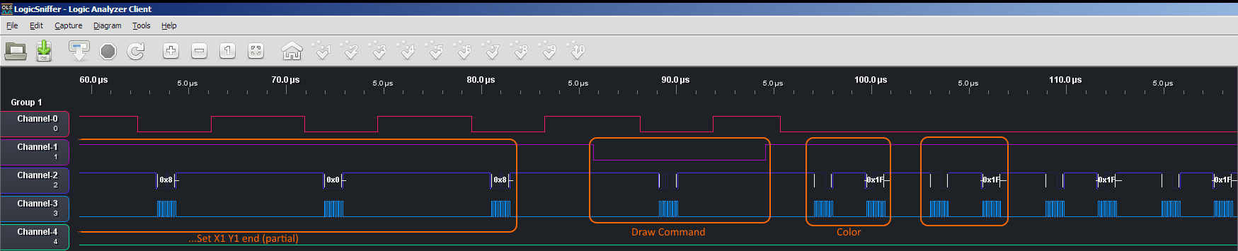
I think I also made a few other minor improvements to some other functions to reduce the number of calls to setAddressWindow (and other some clipping improvements and bug-fixes). The bulk of the speed-up was achieved with the changes outlined above. If you look at the "after" logic analyzer capture, you can see the end result of all this effort.
The same AVR 8MHz SPI bus, but with vastly more bytes transferred in a given time period. This is what allowed a 2.5 to 12 times speedup of various primitives.
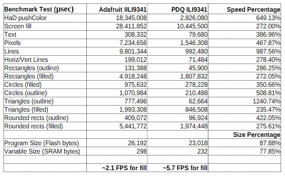
Here is a table showing the output of the included "benchmark" program (included with the PDQ drivers, modified from the Adafruit example). I used my modified benchmark, but switched it to use Adafruit_GFX with ILI9341 and then PDF_GFX with IL9341 on the same hardware (just a few lines changed at the top to switch libraries).

Conclusion
These SPI displays are never going to be "barn burners" on AVR, but they are a great alternative to even slower (and boring) monochrome character LCDs. I am pretty happy with the improvements achieved and I think they help make these low-cost display modules even more useful. The speed is more than adequate for a nice GUI interface or instrument readout (in most cases), and even enough for games without to much screen area being redrawn each frame.
Recently I also made a PDQ driver for the ST7781R chipset as used in Seeed Studio Touch Shield V1.0 (also sold by Radio Shack, from which I got a super cheap deal at a closeout sale). These use a parallel interface, and with some low-level GPIO optimization, these have proven to be roughly about twice as fast as the SPI modules (e.g., the screen fill benchmark is 4,394,756 microseconds which is ~13.5 FPS).
I want to give a shout-out to Adafruit for creating the GFX library and making it open source with a license that makes it possible for me to goof around. Their version is still much better for portability to other non-AVR platforms (and probably easier to understand the code). I will also mention that at this point I now have a nice little collection of various LCD display modules and shields, and the Adafruit ones really are much better quality (displays aren't attached crooked and generally have nice level conversion for 5V Arduino).
More power to you if you actually read through this entire write-up. Hard to make these "software" build notes interesting without the all the "in progress" pictures of a hardware build. :-) Thanks, and I hope you found something useful in all this.