Close
0%
0%

Marauder's Map

A real life player tracking system, that will give users access to a map of everyone else in the area.

Similar projects worth following
This is the Marauder's Map project, inspired from the Harry Potter stories. Our map will take the form of a website that shows the locations of all of your friends or fellow players on a map around you. This map will color indicate "good guys" and "bad guys" as well as where they are. This will give users the ability to set up a video game style "player radar" that they can use during paintball, air-soft or even Harry Potter-esque hide n' seek.

What will it do?
The idea is to create a set of radio "tags" that each player will wear. These tags will broadcast a radio chirp every so often and a network of radio receivers placed around the field of play will triangulate the location of each player. These locations will then be plotted on a map that can be viewed by players.

About us:
John (phreanik) & Clayton (wahwahweewah) are both engineering students at Texas A&M studying electrical engineering and computer engineering respectively.

Time for some technical details!

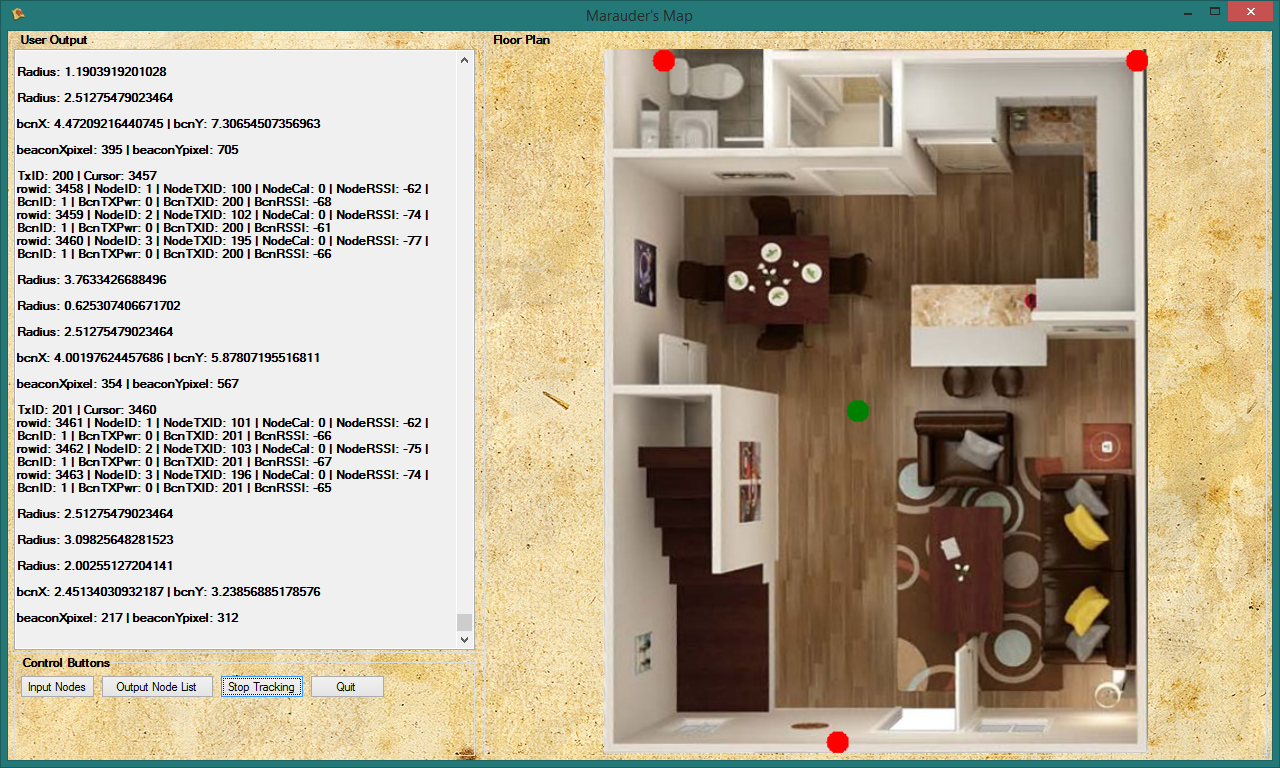
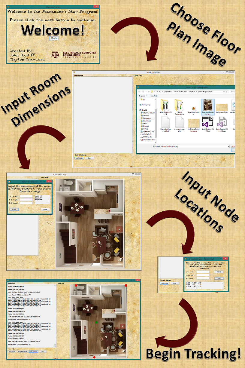
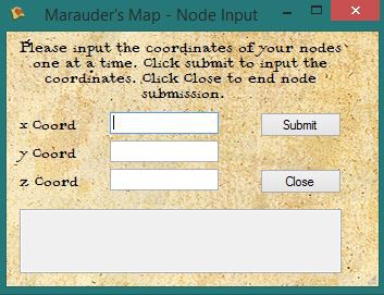
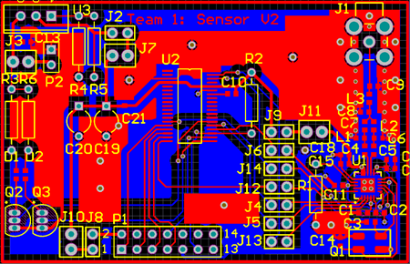
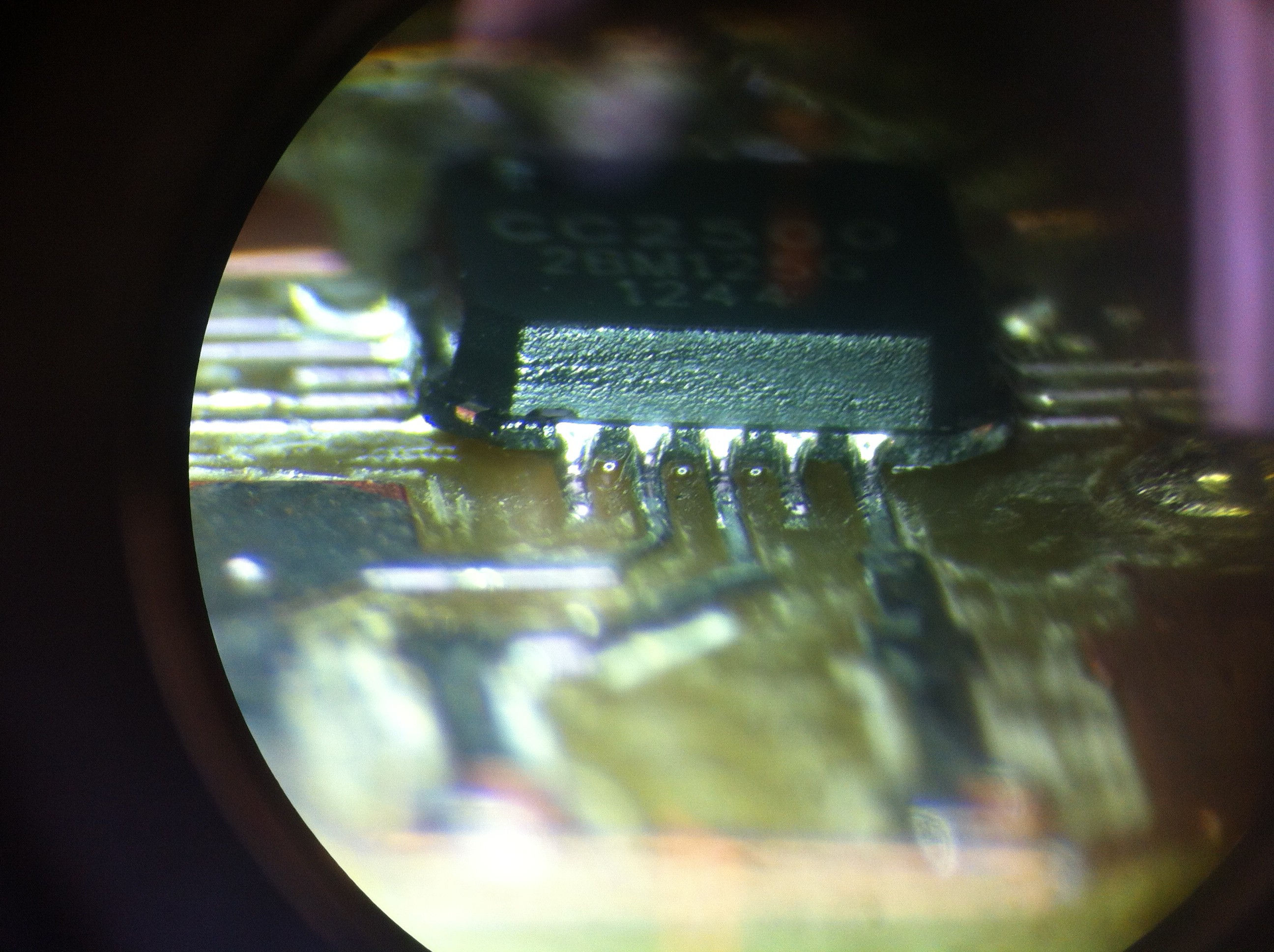
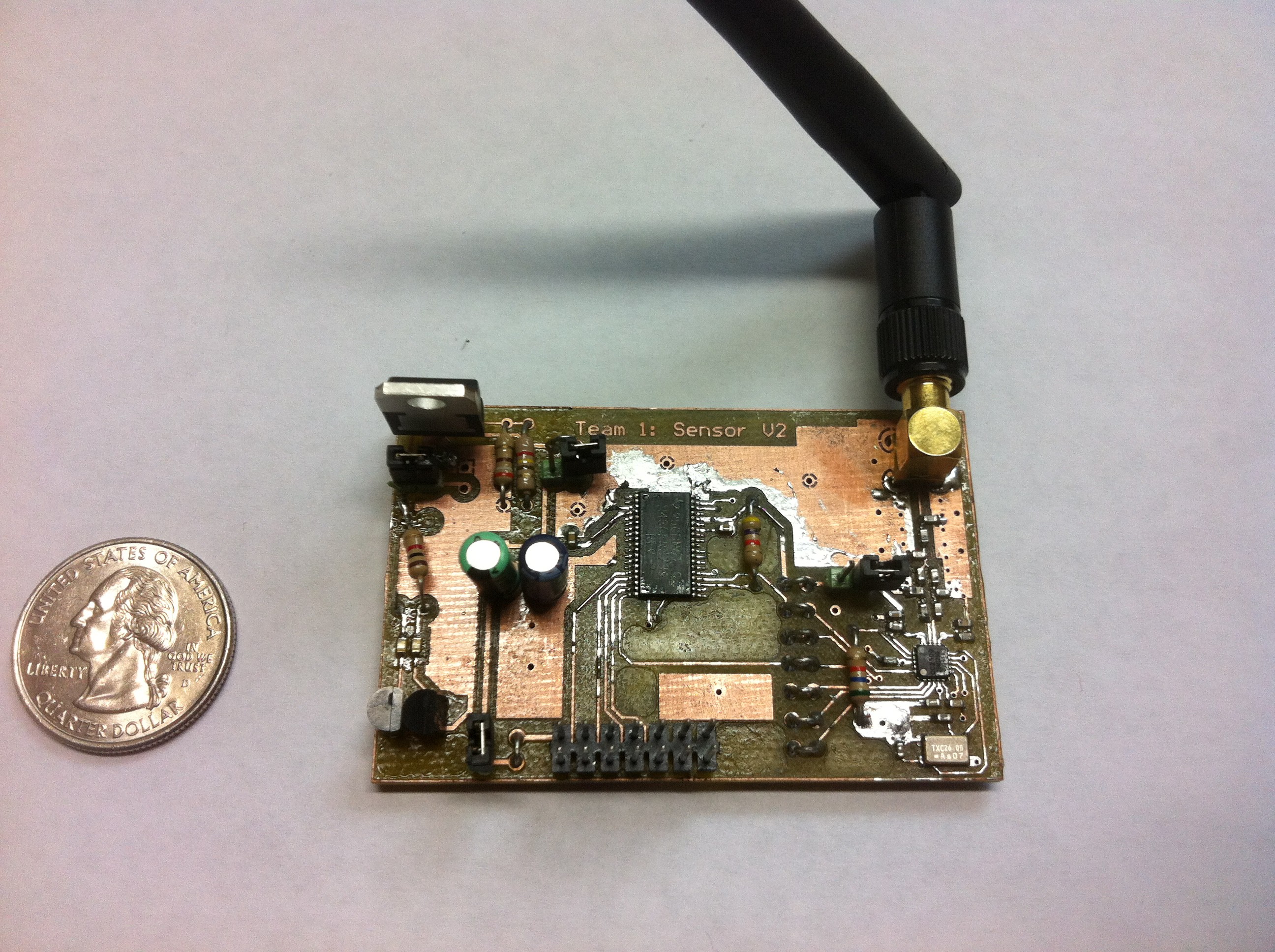
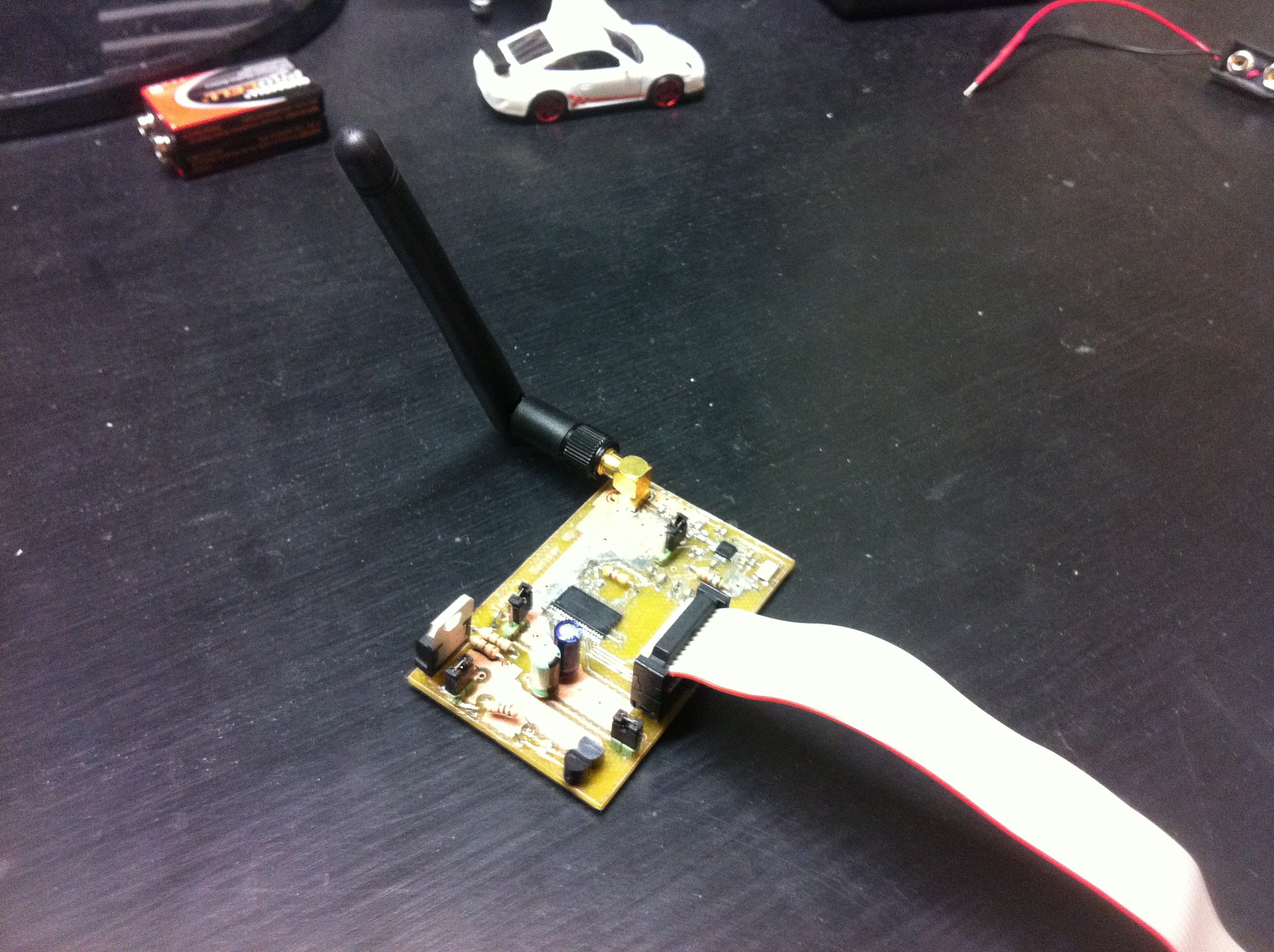
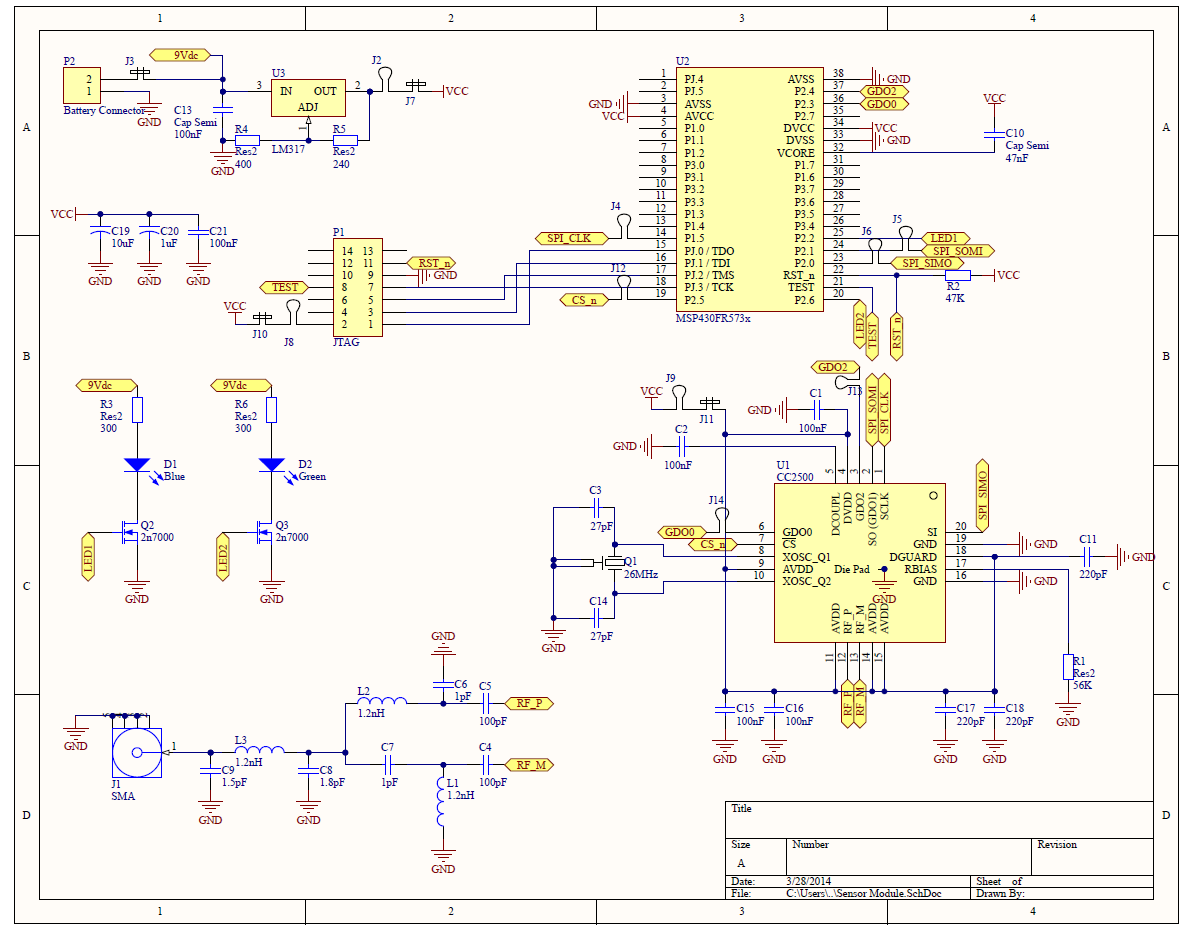
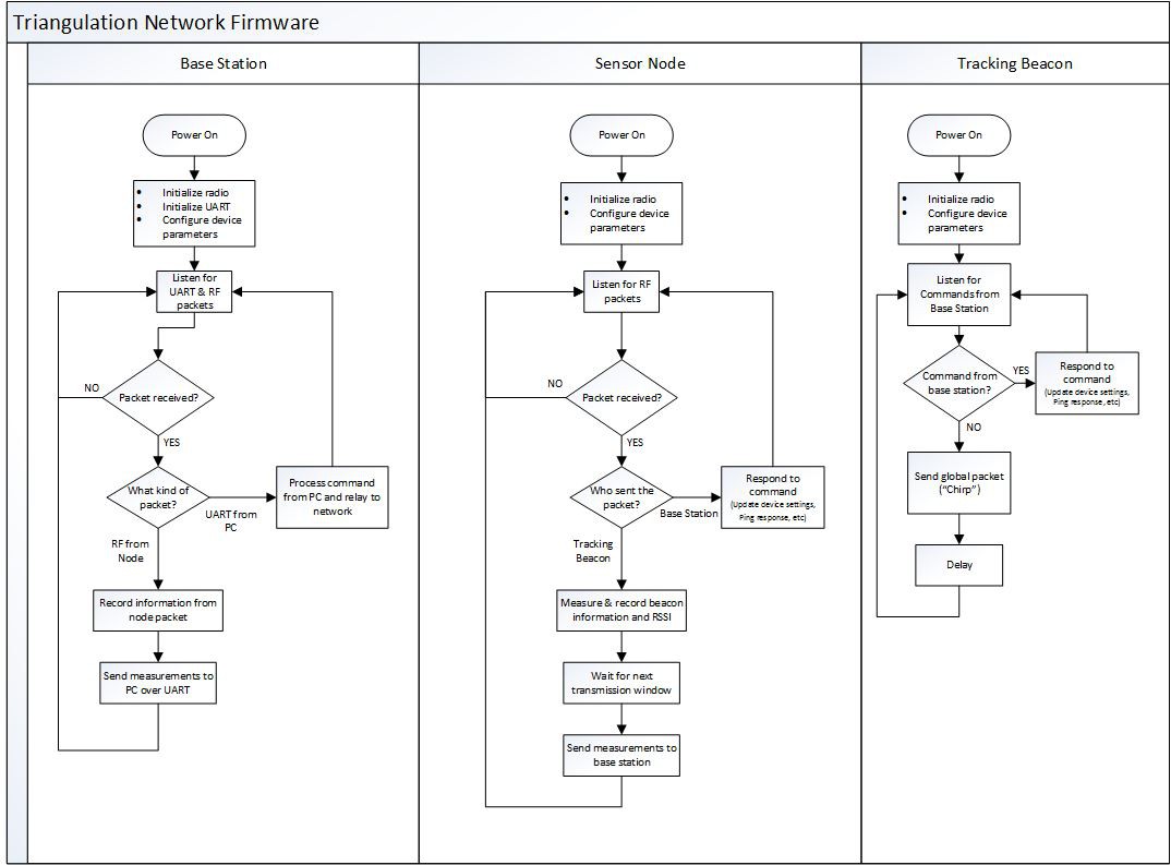
Each "player tag" will be a small self powered PCB with a low power MSP430 and a TI CC2500 radio. These radios will broadcast small packets containing some basic information (Tag No., Player name, etc) that can be received by a network of receiver nodes in the field of play. The receiver nodes will again be small battery powered devices with an MSP430 and CC2500 radio. They will listen for nearby player tags, record the received power of each tag and forward this information to the base station. The base station will be a USB device plugged into a computer, again with an MSP430 and a CC2500. The computer will receive the player tag power information from the network of receivers and triangulate the location of each player. It will then plot these locations on a map and post it online for players to view on their smartphones.

So why not use GPS to find player locations? Well there are a few reasons, but I will narrow the list down to two. First, GPS will not always be accurate or available at all in large concrete and metal facilities where many paintball or air-soft games are held. Second, GPS chips on every player tag would add a HUGE expense to this project, especially since we will still need to use radios for wireless communication. Fortunately, since the CC2500 is dirt cheap and high performance, it solves several of our problems.


Project Tasks:

- Hardware

- Prototype RF communication with EZ430-RF2500 development boards

- Design PCBs for all three types of devices (Player Tag, Receiver Node, Base Station)

- Design firmware to handle communication between devices as well as data management

- Order PCBs, assemble them, debug, debug and debug some more

- Software

- Database

- Code to triangulate player locations from RF power info (Not trivial)

- Code to host website with player locations plotted on a map

  • 10 × MSP430-FR5739 Micro-controller IC Great processing power in a cheap power efficient package.
  • 10 × CC2500 Radio IC Low power 2.4GHz radio IC from TI.
  • 6 × EZ430-RF2500 Evaluation, Demonstration Kits, Boards and Modules / Evaluation Kits, Boards and Modules
  • 1 × Lenovo Laptop Laptop serves as base station

  • Sci-Fi-Contest Complete!

    John Boyd04/23/2014 at 16:38 0 comments

    Well we have finally got this project to a state we feel comfortable calling "complete" for the Sci-Fi-Contest. While any project of this nature can always be revised and improved, we now have a fully functioning system that tracks your location and displays it on a map! Below we will have a video demonstration.

    Summary of project:

    The project uses a network of TI EZ430-RF2500's to measure the signal strength of a tracking beacon inside a building. We demonstrate our system using 1 tracking tag, 1 base station receiver & 5 receiver nodes and only a 1Hz location update rate, but this can easily be expanded to have hundreds of nodes and many tracking tags. The update rate can also be increased, but we had it running slowly for other tests. The network nodes measure the signal strength (RSSI) of the locator beacon and send this signal strength information back to the base station. The base station hands this data over to a python script that pushes all of the information onto a database. Finally, a C# GUI application gathers the information from the database, calculates the best approximate location of the tracking tag within the room and displays it on a map.

    Video:

    Demo Video

    Some notes about the video:

    •  Sorry about the random circles and lines appearing on the map. We had these displaying for debug use and forgot to turn them off.
    • You may notice the green dot bounces away from the actual position a few times (even off the map once). This is because of RF interference in the room. It turns out RF tracking inside a room like this is a non-trivial task. Our system recovers relatively quickly though and starts showing an accurate location again.

  • Testing, testing and more testing

    John Boyd04/17/2014 at 18:54 0 comments

    So as Clayton mentioned in the previous log, we pretty much have the entire system integrated and now it is time to test, debug and improve. We have been testing the system in different environments, and have had interesting results. While the results are certainly not as reliable as we would like them, we do get results that are "in the ball park". 

    Just a little hardware update: I resolved several issues with the hardware, most notably porting the firmware from the EZ430-RF2500 platform to our custom platform, but a few issues still remain. Unfortunately, since the project works decently just using the EZ430-RF2500 boards and time is running out, we will be sticking with these boards for the proof of concept, and may come back and finish up the custom hardware once the project is completely working.

    We are well on our way to wrapping this project up. We mainly need to improve our distance calculations between the receivers and the tracking tag. Once we work that out, the system should work much more reliably. Stay tuned for progress!

  • The Green Dot of Success...

    wahwahweewahh04/14/2014 at 20:22 0 comments

    The software has seen a lot of improvements since the last update. First of all, we officially have tracking. The screenshot below shows three nodes (red dots) and one beacon (green dot). The program can process data in real time and is currently only limited to how often the nodes send data to the base station (1Hz). When the 'Start Tracking' button is pressed, the program will make the following query on the database: 

    'SELECT * FROM Data WHERE BcnTXID = transactionID AND ID > cursor' 

    Since John incorporated a transaction ID, I can choose groups of readings easily by selecting a certain transaction ID. The cursor handles placement within the database, making sure previously selected rows aren't selected again. Once the database returns the resulting tuples from the database, if there are more than two rows the program can begin triangulation. The program then runs through various calculations in order to return a coordinate for the beacon (green dot). 


    The image below just shows a simple program flow that the user would take when running the program. The user sees a welcome screen and clicks the Next button to go to the main program window. From here, the user must select the Load Image button in order to load a floor plan image. As soon as the user selects and opens the image, another window appears to allow the user to input the dimensions of the room. The user is led back to the main program window where they can output the list of nodes and begin tracking. 

    Overall, the project is complete, however there is room for some slight improvement and modification that will be looked into by John and I. 

  • SQLite and Concurrency

    wahwahweewahh04/03/2014 at 03:19 0 comments

    Just a little minor update this week. I have successfully integrated SQLite into the visualization program (C# - WinForms) as well as the Python script that handles reading the PC's serial port. Instead of writing serial port data to a file, the plan is to parse through strings of serial port data and push the data to a local SQLite database. The visualization program will read tuples from the database and begin processing. One of the fields in the database corresponds to a row identification number and will be used to tell the viz program where to read the next tuple. Since the viz program knows the last row that was read, I can perform a query to only (SELECT * FROM Data WHERE rowID > currentRow;) get rows that have been added after. If the result returns NULL, then we know there has been no new data added to the table.  

  • Countless hardware troubles!

    John Boyd04/02/2014 at 01:34 0 comments

    It has been a while since I posted a project log, so I thought I would give an update. I have been working hard trying to debug several issues on our assembled board. For some reason I cannot get the SPI communication between the MSP430 and CC2500 working. At first I thought the CC2500 got fried during soldering, but now I am severing the SPI wires and watching them on the scope, only to see that the SPI clock isnt even being driven by the uC. 

    The problem with this is it could be a firmware issue (The SimpliciTI SPI APIs are deep and complex) or I may have broken the eUSCI module on the MSP430 if I accidentally overcooked it during soldering. Given that both of these problems are tedious to solve, I will be focusing on integrating the firmware better with Clayton's software and we can just use the EZ430-RF2500 devices to demo the project for the Sci-Fi Contest. Once the firmware is solid, I will come back to debugging the hardware, but PCBs may arrive after the contest has ended. Dont worry, we will continue to update this project LONG after the contest is over :)

  • Software is in the works!

    wahwahweewahh03/29/2014 at 00:11 0 comments

    Hey guys, just wanted to let you all know that the software side of this project is in the works also. (source code here) I (wahwahweewahh) have chosen to go with a C# program, because of the awesome GUI tools this language offers. Microsoft's Visual Studio is also a great platform to quickly try out different GUI ideas without having to dive down into the inner workings of the code.

    Got ourselves a fancy map styled welcome screen :)

    This is the layout I am playing around with for the program. A map of the field will go on the right side in place of my picture.

    I also added a form so that we can add receiver nodes to the network. I have also been writing code to deal with incoming data from the sensor network. Currently I have a python script that receives data from the network via USB and stores it to a file. I have been playing with the data in Excel trying to formulate a good algorithm to calculate the distances between each sensor node and the tracking tags. Once I know these distances, it is just a matter of solving a few algebraic equations to triangulate the location of each tag. Python will most likely not be a permanent solution, but it is working for now as a proof of concept.

  • Hardware is coming along.

    John Boyd03/26/2014 at 03:51 0 comments

    I made some rough PCB prototypes for the board a while ago, just to test the radios, micro-controller and firmware together. You can see a picture of the Altium board file below. I had the Electrical Engineering Department at my school (Texas A&M) mill the PCB to test. If the PCB works as expected, I will modify the board and send out to OSHPark (or similar) for a more professional run.

    I spent hours soldering the tiny SMD components on (0402 SMD inductors, 0603 SMD Caps, etc), especially the CC2500 which I was only able to get in a QFP package.  

    This little fella was NOT easy to hand solder! You may notice some pretty terrible copper patterns in the picture above. This was actually a milling error that the PCB mill at school did. The final product will be ordered from a fab house and will have no such issues.

    Finished soldering first prototype

    Here are some pictures of the board soldered up and ready for programming and testing. Now that the board is assembled, I will be focusing on debugging any hardware issues and then porting the firmware from the EZ430 to this board.

    I have a lot of extra test loops and jumpers in this circuit for debugging, but my final circuit will not have any.

  • Firmware Ahoy!

    John Boyd03/25/2014 at 04:32 0 comments

    We now have a first draft for firmware for all three devices!

    After spending about a week playing around with the EZ430-RF2500, we finally have something to show for it! We have three build configurations in Code Composer Studio each with a first draft firmware for all three devices using TI's SimpliciTI protocol stack. The Player Tag is broadcasting its basic info (Tag ID number, broadcast strength and packet number). The receiver nodes are receiving these packets, measuring RSSI and forwarding that to the base station. The base station is capturing this data and immediately streaming it to the computer via USB serial interface provided by the EZ430. The code can be found here.

    Issues:

    I spent several hours debugging packet collision issues. At first I did not know why none of our packets were being received, but after a bit of thought we realized that all of our packets were transmitting at the same time and interfering with each other. To fix this I gave each device a specific time to transmit based on its device ID, ensuring that no two devices tried to transmit at the same time. While this is working, it is not very efficient and slows the total packet rate the network can handle.

    What next?

    Now that we have a basic implementation of the system on the EZ430 development boards, it is time to start designing some PCBs. Dont get me wrong, I still have tons of work to do on the firmware (specifically improving the communication strategy), but it is a great start! Now that I have data flowing to the computer, Clayton (wahwahweewah) has some real data he can work with as he develops the software.

View all 8 project logs

Enjoy this project?

Share

Discussions

Jasmine Brackett wrote 08/07/2014 at 19:50 point
Hey phreaknik and wahwahweewahh, as Adam mentioned you need to add a few more details to your project to give it the best chance of going through to the next round of The Hackaday Prize.

By August 20th you must have the following:
- A video. It should be less than 2 minutes long describing your project. Put it on YouTube (or Youku), and add a link to it on your project page. This is done by editing your project (edit link is at the top of your project page) and adding it as an "External Link"
- At least 4 Project Logs (you have this covered)
- A system design document (you should link to these from the Details section, so we can find them easily)
- Links to code repositories, and remember to mention any licenses or permissions needed for your project. For example, if you are using software libraries you need to document that information. (You are looking pretty good on this front, just make sure they are up-to-date)

You should also try to highlight how your project is 'Connected' and 'Open' in the details and video.

There are a couple of tutorial video's with more info here: http://hackaday.com/2014/07/26/4-minutes-to-entry/

Good luck!

  Are you sure? yes | no

Adam Fabio wrote 07/15/2014 at 05:15 point
Thanks for submitting The Marauder's Map to The Hackaday Prize! I know you finished up your project awhile back for the SciFi contest, but don't forget to upload the videos and any new information you have!

  Are you sure? yes | no

grummelBit wrote 05/09/2014 at 16:00 point
The Fraunhofer ESK has the same project called "ENLOK" http://www.esk.fraunhofer.de/en/projects/ENLOK.html
Did you measure which accuracy you can obtain(fixed/moving)?

  Are you sure? yes | no

John Boyd wrote 05/12/2014 at 00:50 point
Its interesting you mention that project. A researcher for that group actually invited me to help out with their research after seeing our project!

To your question:
Short Answer:
Yes and no. We attained an accuracy of around 2.5m - 5m in our particular setup, but the way the system works, the accuracy is entirely dependent on several variables that make it difficult to say "our system will deliver this level of accuracy for your scenario"

Long Answer:
First, the more nodes you use, the more accurate the system gets. Second, the geometry and construction of your environment (concrete, metal, walls, pillars) and where you station your devices within this environment has a huge affect on the accuracy of the system. Finally, the third and biggest challenge with our system is the constantly changing 2.4GHz interference from other devices. In buildings with many WIFI routers or bluetooth devices, your performance can be heavily dependent on how many of those devices are in use at any given time. This means during business hours with heavy WIFI use, accuracy may be significantly worse than after hours.

  Are you sure? yes | no

biohazarus wrote 05/08/2014 at 20:46 point
Hi, what are the plan for this project?
Are you planning to complete it or will go on the ToDo list of never completed projects (no judging here just asking)
Would really like to get my hand on one of those( or multiple to be more then one on my map) :P
Currently I do not have lots of spare time, but hopefully thing will slow down and I would be more then happy to give a hand.

Take Care,
Alex

  Are you sure? yes | no

John Boyd wrote 05/09/2014 at 04:13 point
Well I really would like to see this project come to completion, but there are some inherent challenges that we have come to learn about this project that make this answer complicated.

First, yes. I definitely plan on furthering this project and making it better.

Unfortunately, as we have discovered after spending so much time testing and trying things with this project, we have realized that the location resolution will never be as good as GPS. This means we have to check our expectations and reconsider some of the principles behind our system, but yes, we certainly hope to improve the system and make it more useful :)

If you have any questions or need advice implementing or testing our system on your own, feel free to ask. I will do what I can to help others repeat and further our work!

Thanks for your support! :)
John

  Are you sure? yes | no

Bubble wrote 04/10/2014 at 12:06 point
Hi guys, im just curious how accurate you can be with this radiosystem? I am looking for a system that can give me a very detailed position in an open area. i was considering GPS but its not accurate enough. i need an accuracy of a few centimeters in a field that can be as big as a footballfield.

  Are you sure? yes | no

John Boyd wrote 04/10/2014 at 16:03 point
Well the way we are designing it, the precision will be comparable to GPS, but we probably wont spend a lot of time improving it beyond that.

Really it comes down to how you want to calculate the distance between the tracking tag and each node. The equation to do this is very complicated, so we are going to use a look up table of distance values that correspond to different distances. Using a look up table obviously limits the precision of the system.

If you want to improve the accuracy, there are two choices:
- Use a much larger look up table with much better resolution
- Use a DSP and develop algorithms that can quickly and reliably solve the logarithmic RF power equations

Due to background RF noise and other environmental issues, the power readings will fluctuate some, so for a more precise reading, you will want to take several averages of the power reading every time you try to locate the device.

Hope this helps. I could talk forever about this, so if you want any help, feel free to ask away.

  Are you sure? yes | no

Eric Evenchick wrote 03/27/2014 at 20:46 point
Awesome project! Just wondering if you could export PDFs of the schematics for people who don't have Altium installed. The CC2500 boards look very interesting, and I'm sure the schematics could help others building Bluetooth hardware.

  Are you sure? yes | no

John Boyd wrote 03/27/2014 at 21:43 point
Good idea. I will add pictures of the schematics to the hardware project log. I dont think the site permits PDFs though, right?

  Are you sure? yes | no

John Boyd wrote 03/27/2014 at 22:25 point
Also, just for reference, the CC2500 is not bluetooth compatible. It is much cheaper this way allowing us to build a huge network on a budget. The downside is you will have to find a protocol stack solution (TI Simpliciti works great).

  Are you sure? yes | no

forestpt wrote 03/26/2014 at 21:24 point
would this work as a tracking device in a contained area? For example, take your child to the Mall, put a wrist band on the child that transmits. If the mall were outfitted with the tracking system, then you might not ever have a truly lost child again.

  Are you sure? yes | no

John Boyd wrote 03/26/2014 at 21:35 point
It definitely would. Indoor tracking is the perfect application for this project. This is an awesome idea I hadn't thought of!

  Are you sure? yes | no

Smileystyle wrote 03/26/2014 at 21:02 point
Could this be used at Universities for something like a Zombie vs Humans game? Would it be cheap enough for people to fund their own tags that have a switch on it to change their signal from human to zombie, or Team 1 to Team 2, if they die?

Right now they use bandannas to signify what team they are on, but a system like using the marauders map would be so much cooler.

  Are you sure? yes | no

John Boyd wrote 03/26/2014 at 21:04 point
The target price for the tags is about $5 per unit, and adding a button to the tag would be easy enough. I like this idea! I will definitely look into adding some buttons to the Tag.

  Are you sure? yes | no

Dfwz33 wrote 03/25/2014 at 22:55 point
How do you plan on determining which players are "good guys" and which are "bad guys" when each player looks on the map? For example, if all the players can open the webpage and see the map, how do you know what color dots to put on the map?

Also, will every player be able to see every other player on the map, or just those on his team?

  Are you sure? yes | no

John Boyd wrote 03/26/2014 at 03:40 point
As far as good guys and bad guys goes, the players will join teams at the beginning of the game by putting their player tag ID in on the base station.

As for knowing which players are your teammates or "bad guys", we will probably put a simple login on the website, so that the map knows which player is looking at it and knows what color dots to show.

For your last question, we haven't decided yet, but we will likely add several game modes that the user can choose from.

  Are you sure? yes | no

Similar Projects

Does this project spark your interest?

Become a member to follow this project and never miss any updates