 deʃhipu
Remember that time when you sat on your leg for some time, and it got numb, and when you got up, it felt all wooden and walking was like walking on stilts? That's how most walking robots feel. What happened is your nerves got squished and blocked a little, and you lost your sense of proprioception -- the position and forces of your limbs. Now you know why robots that don't have force and position sensors on them have such a hard time walking!
What if we could add this sense to our robot? It would still be blind and deaf, but at least it would have a sense of self. It could feel its way around, knowing if a leg is standing on the floor or floating in the air, knowing if there is something blocking its movement. If we got smart with programming, we could even make it "obedient" and go in the direction you push it, just like this robot:
OK, well, maybe not as well. After all, we have limited budget and time. Plus programming the algorithm that calculates the overall force from the feedback from all the joint could be a challenge...
But at the minimum we could make our robot stop when it arrives at the edge of the table and tries to put one of its legs in the abyss beyond it. Or when we pick it up.
So how do we do it? We could attach additional sensors to the legs -- encoders for the position and pressure sensors for touch and force. I checked the parts -- they are either expensive or problematic to mount on such a robot. But wait, doesn't the hobby servo already know its position? Why not use that?
The first approach was to use an additional wire added to the servo's potentiometer to read its position. I used this excellent guide on modifying the servo. It worked. Kinda. But not as well as I hoped. The problem is that to deduce what force is applied on the leg, I need to calculate the difference between the desired position of the servo and the actual position. This difference is going to be small, because the servo's electronics are working hard to correct it. Turns out that they are smaller than the noise, even if I add filtering capacitors and software filters. Oh well.
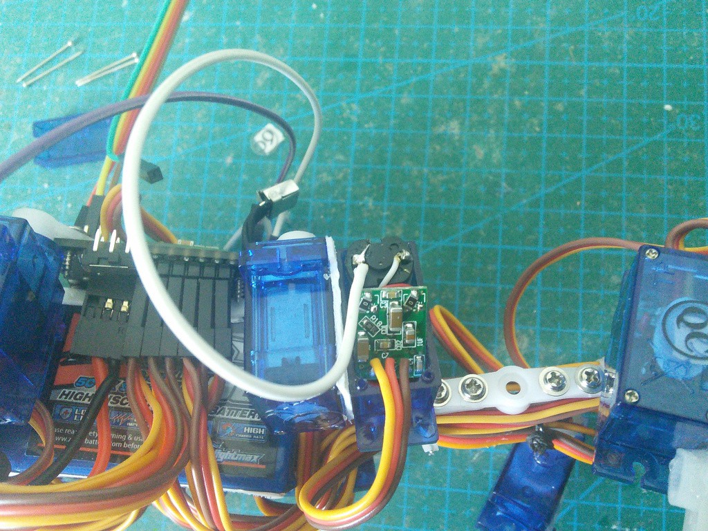
Then I realized that the servo's electronics is actually already calculating the force, for its own purposes. Can I somehow plug into that? What if instead of reading the pot's position, I would simply read the voltage that the servo is applying to its motor? Turns out that this works quite well, at least with the SG90 servos that I have. Here's an experiment that I performed to test a "compliant motion" servo:
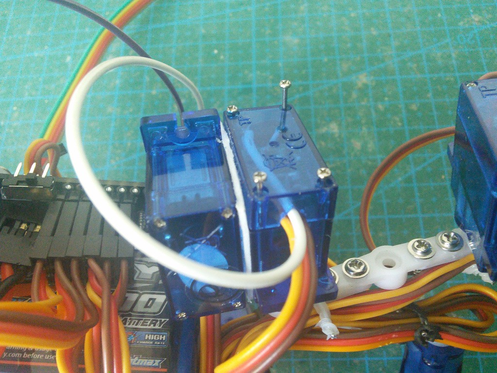
I soldered an additional wire to the servo's motor, like this:
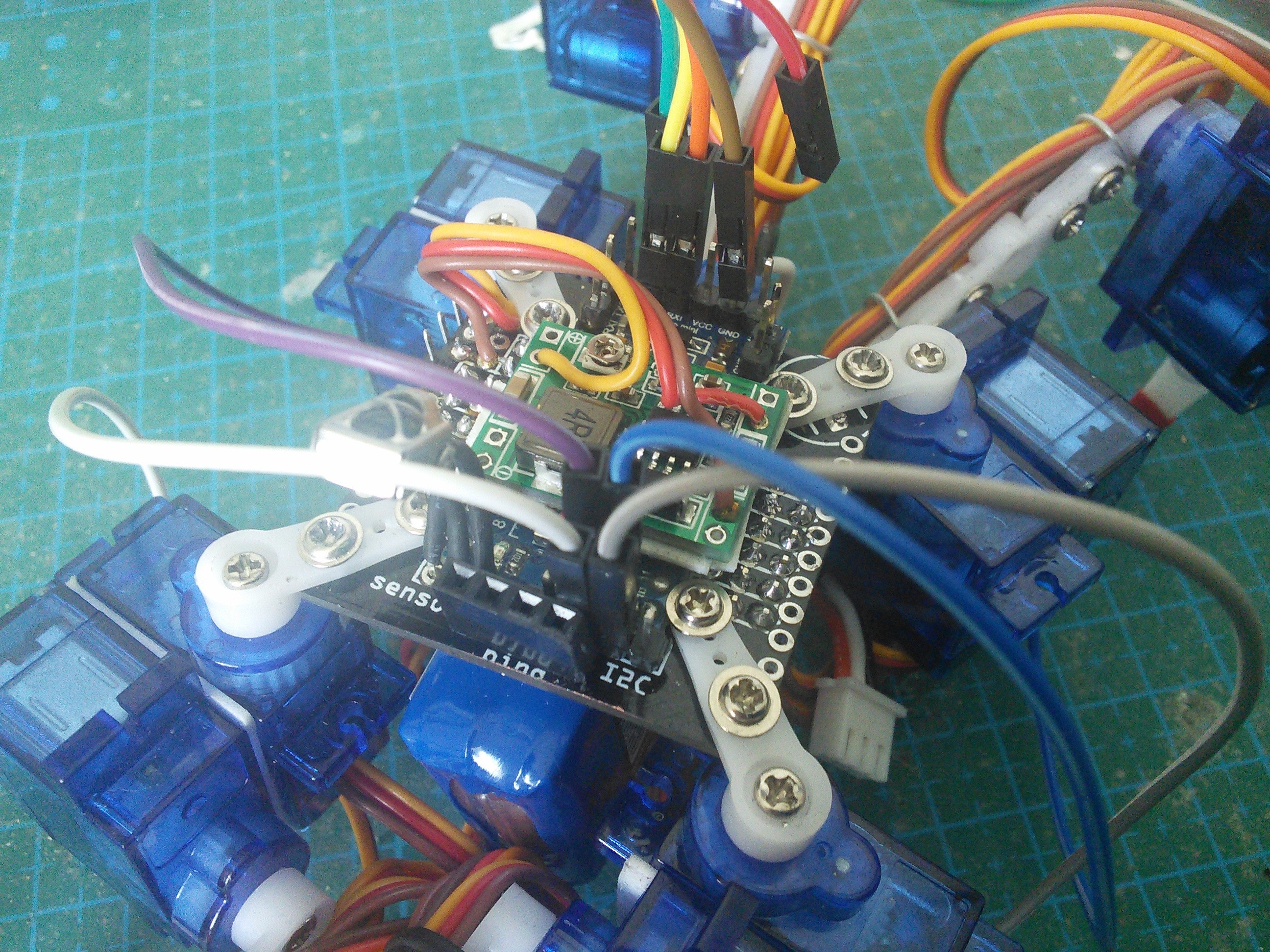
Now just a simple addition to the walking algorithm. Every time you put your leg down, wait for the servo to get there, and then read the force from it. If the force is too small, stop. I also made all the other legs move up slightly just before the reading, to shift the weight more to the leg that we are interested in. The result is not very pretty yet, but I'm sure I can tweak it to look better:
With some tricks, I might even be able to make it walk on uneven terrain without additional endstop switches at the ends of the legs.
Update 2015-06-10:
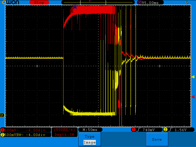
A friend of mine ran some of those servos through an oscilloscope, to see how the voltage on both of the motor wires looks like. Here's the servo going one way, stopping for a moment, and then going the other way:
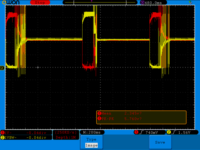
You can see that when stopped, the motor floats at about 2.3V, and goes up to 5.7V or almost to 0V when moving. You can also see that there is quite a lot of oscillating at the end, when it overshoots and corrects:
An interesting thing happens when you reverse the direction without stopping:
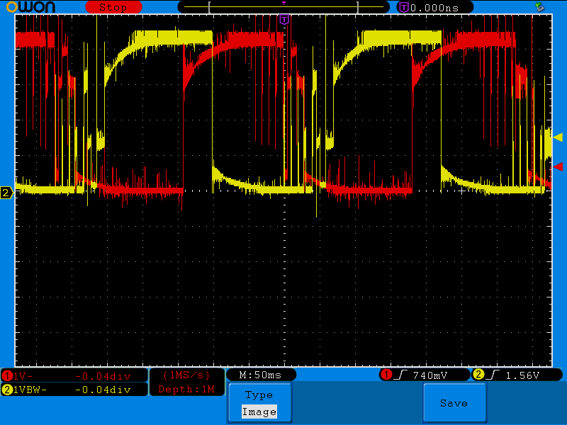
One of the motor leads gets high voltage long before the other gets low. Since what drives the motor is the difference, this gives the motor some time to stop and reverse, before applying the full force.
Discussions
Become a Hackaday.io Member
Create an account to leave a comment. Already have an account? Log In.
Not sure I've analyzed that last photo (reversing-direction) completely, but having the two outputs at the same voltage (either high or low, not floating) is often referred to as "braking." The voltage they're set to doesn't really matter (unless e.g. the high vs. low-side mosfets differ in on-resistance). It's essentially shorting out the motor-windings, which, basically, causes it to stop spinning quite quickly.
Though, I'd think reversing the windings would cause it to stop much *more* quickly, no? Not sure about that, maybe it's about smoothing the motion; allowing it to stop before reversing, rather'n slamming immediately into reverse... Oh, right, *that's* what you were saying ;)
Are you sure? yes | no
Please note that we are not seeing what the IC is supplying to the motor, but whet the voltage on the working motor is. So it may be as well voltage induced by the motor's breaking.
Are you sure? yes | no
I was doing some work on getting feedback from micro servos today, and figured out the reason you get much better performance in compliance when pushing one way than the other. (In the video you can push it to the left more easily than the right).
My batch of SG90's use the AA51880 which does a rather sneaky trick. When it needs to move the servo a lot it drives one side of the motor to ground and the other to power (as expected), but when it only needs a move it a little bit it seems to leave one side at the middle voltage. This is rather inconvenient as it means there is no single place to extract a force from.
What I have done in the past is to measure the current going to the servo by putting a low value resistor in series with it. This still is pretty noisy, and you can't tell what direction force is applied in but it works equally well in both directions.
Also, measuring the position (via tapping the potentiometer) and comparing it to where you told the servo to be can also give an approximate force. I found this to be a little more reliable than tap to one side of the motor.
Are you sure? yes | no
Hmm, to be honest I don't remember there being a difference, I think that it's just that my thumb is much stronger than my index finger. I have several batches of SG90s and each and every batch has completely different electronics inside, so this can vary a lot, of course. You are right that I should be measuring the difference between the two wires of the motor, not one against the ground, but that complicates the setup considerably. I will see how my smartservo project works out, that would solve all the problems at once.
Are you sure? yes | no
[this comment has been deleted]
I don't even know how to measure it, but I suspect there is plenty of time left. Since the servo control signal is 50Hz, it doesn't make sense to do more than 50 FPS. I think I'm doing 10 FPS at the moment, because the servos are pretty slow anyways.
If that gets too slow, there is plenty of room for optimization. I'm using the default floating-point trigonometric functions -- those can be swapped with fast integer alternatives.
Finally, you can always put something like a teensy in there instead or in addition.
Oh, and I'm not doing force-sensing every frame. At the moment I'm only checking it just after the leg has been placed on the floor, to check if there is indeed any floor in there.
Are you sure? yes | no
whoops.... tried to fix my not replying properly. Original question: Cool. Do you know what percentage of the cycles you're using for the full loop with force feedback at the moment?
OK, at 10fps there should be a good deal of room for improvement. At some point it will need a bigger processor or to move the modeling to but you should be able to do a fair bit more filtering on the arduino (a simple 2 or 3 variable kalman filter that integrates force to motion might give some really good results). In the short term, maybe you could sum the hip and knee loads to get a composite load measurement with a little less variance? It should increase the sensitivity a bit.
Are you sure? yes | no
Oh, it's not obvious from the article, but I only had 4 spare analog pins, so I'm only monitoring the hip servos (as they carry the most of the robot's weight). Of course, for stuff like compliant motion you would need 12 analog pins, so you would probably need to add another board. I will have a log soon about adding more boards on top of Tote, including a Teensy 3.1, which has a lot of analog pins.
Are you sure? yes | no
I had a play around with this idea on one of my servo's. Some observations:
- It's a PWM signal (which I'm guessing you know) so you either need to look at the peaks or integrate fairly smoothly over time. Sampling at 1ms for 50 samples gave me really clean data with tiny noise (the detection dead zone with tuning is about 1.5 increments on the ADC input scale, so v. sensitive).
- There's a small voltage offset turning the motor from one side to the other on my motor. Correcting for this massively increased the sensitivity and reduced the bouncing somewhat.
- Without a model of velocity and the PID loop, debouncing over multiple samples helps get rid of controller related noise (ie continue testing until 3 tests in a row agree). I think this could help the foot contact detection a little.
I'm a bit busy with work at the moment but when I next have some time I'll see what I can do with the motor controller response - there's a lot more information that could help with compliance.
Edit: one thing that others may be interested in is that the motor in these micro servos floats higher than ground, so you can measure bidirectional motor actuation with just one wire. Handy!
Are you sure? yes | no
Thank you for looking into it! As far as I know about the internals of the servos, it is indeed a PWM signal, and at the same frequency as what you are driving it with. There is a PWM generator inside that generates signal based on the pot position, and then that signal and your input signal are compared and that goes into the motor. Not sure if we could use that somehow.
I could probably use a digital pin instead of analog pin to read that signal -- measure the duty cycle of the PWM instead of the average voltage. It's only 50Hz after all.
I didn't think about the offset, that's probably my measurements had such a huge error on average -- I was measuring both directions together. I will need to repeat that with each direction separately.
Good idea about debouncing to make sure the servo is stopped. I could use that for a "move the servo to this position and wait until it gets there" command, which is better than the hardwired delays that I have now.
I think they made the motor float to save on mosfets.
Are you sure? yes | no
This is very cool. Force feedback could change hobby robotics. What's the noise and read rate like? I noticed you had a little oscillation in the compliance test - is that just a matter of tuning the controller or is it a bit too noisy?
Are you sure? yes | no
I didn't make any formal calculations -- because I'm a hack, not an engineer -- but the analog pin readings from a resting motor is around 730, +-10 with some basic filtering (average of 40 readings). This can go up or down (depending on the direction) by as much as 200 under load. It changes by about 20 when the leg is supporting the robot (it's relatively lightweight).
The oscillation in the test is because the program I wrote was extremely primitive -- basically, I just checked if the force is above or below a threshold, and if it was, moved the servo in that direction with speed proportional to the force. And because I also measure the force when the servo gets a new position and tries to move into it, it started to interact with the servo's own internal PID in funky ways. I'm sure that a smarter person could write a proper PID controller and tune it correctly and have it run smoothly, but then again, what do I know.
The fact that you can't really measure the force properly when the servo is moving into a new position is a bit of a problem, but I don't see a solution to it without either replacing the servo's electronics and driving it directly with your code, or emulating the servo's own electronics in your code and somehow subtracting its results from your readings. Both are theoretically possible, I guess, but require much more work and smarts than I'm willing to devote right now.
Are you sure? yes | no