 Christopher Hiller
This clock is made to run on either 9-12V DC input. It features a battery backup.
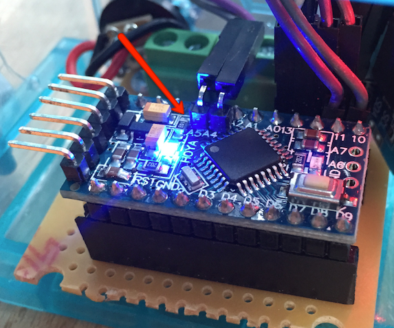
The two 1N4007 diodes are run from the positive voltage of each input to the VIN in of the Arduino. Whichever input has the highest voltage "wins". The 1N4007 will work fine at 1A, but probably not a good idea to try a stronger current w/ these diodes. A 0.1uF ceramic cap between VIN and GND is for protection when one of the power sources is removed.
There are no batteries in the pictures at the moment, because seemingly you need a bit more than 6V to run both the Arduino and the LED display--I only had one 2x CR2032 battery holder on hand and was too lazy to wire up a 3rd coin cell in series.
You could use a 9V battery coupled with a 12V DC input if your box is large enough. I'm not sure exactly what voltage is necessary to make this work, except that 6V is not enough and anything over 12V is too much.
The source code is on GitHub at boneskull/arduino-clock-in-a-box. I've made some modifications to it that haven't been tested, so it may need some tweaking. A caveat to note is that 12:01 AM will display as "1"--need to spend more time with the Adafruit_LEDBackpack lib and figure out how to pad with 0's.
Software Libraries
Tools
- Soldering iron
- Drill press
- Wire cutters
- Wire strippers


 Insight Machines Lab
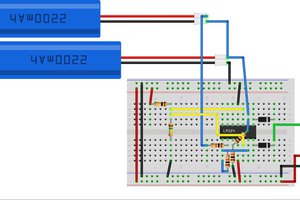
 Dave
Dave
 PointyOintment
Your git link has an i in the box.
What are the diodes for?