Close
0%
0%

Low-power environmental data logger

Small battery-powered data logger that runs on 3.2 µA when measuring at a 1 minute interval

Similar projects worth following
We recently expanded our house and to determine whether or not we need to ventilate more often I made this environmental data logger.
It measures temperature and humidity, with a configurable interval between one minute and an hour and a resolution of 0.04°C and 0.024%rH. The storage lasts for 41.000 measurements and the battery will last for a lifetime (disregarding self-discharge).
The software uses many features of the ATMega88 microcontroller, including sleep modes, power management and timers (including the watchdog timer) and makes heavy use of interrupts to reduce power consumption to a minimum.

This project could also be used in a variety of other ways:
-adjustment of heaters / air conditioning to conserve energy
-monitoring of sensitive objects (animals, food, equipment...)
Also, the sensor could easily be replaced to monitor many other things (electricity, water...)

Circuit

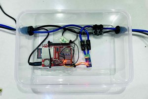
As mentioned, the main processor is an ATMega88 which runs on it's internal 8MHz oscillator.

The power supply is backed by a 220µF capacitor originally intended to last just long enough to transfer all data to the EEPROM in case of power loss. With the new firmware it will last up to eight minutes when sampling at one sample per minute.

The DS1337 RTC is backed by a separate 220.000µF GoldCap. It provides both date and time as well as a one-minute interrupt to trigger a new measurement. It shares the I²C bus along with the 1MBit EEPROM and the HYT939 sensor. To minimize current consumption, external 100k resistors were used as pull-ups for the bus, in my tests they were still sufficient up to a clock rate of 400kHz. Using such high-value pull-ups is not recommended but with such short traces it does not matter too much.

The LCD and the contrast-setting potentiometer are powered from one of the ATMega's pins, so they can be completely powered off and don't drain current continuously.

PCB

The PCB was fabricated on a Shapeoko 2 CNC machine, the layout is single-sided with just nine jumper links.

I used many SMD components, the main processor is housed in a TQFP-32 package and all resistors are 1206s.

I managed to fit all components on a 50x85mm sized PCB.

Case

The case is made entirely from 4mm thick plywood and was also routed on the CNC machine. It uses finger joints and is held together with glue.

It is divided into two sections, the main section for the circuity and a battery compartment with a sliding lid.

The back plate is a press-fit for easy servicing.

Software

The software underwent a complete redo, so I included information on both the original and the updated version in the project logs.

PC Software

Right now, the software used to receive and process the data on the PC is pretty crude but works so far.

It is written in C#.

The data can be saved to either a .csv or to a html file which uses HighCharts to plot the data

  • 1 × Atmel ATMega88 Main microcontroller (TQFP-32)
  • 1 × Microchip 24AA1025-I/P 1 Mbit serial (I²C) EEPROM (DIP-8)
  • 1 × Hygrosens HYT-939 Digital humidity and temperature sensor, 14bit resolution (TO 39)
  • 1 × Maxim DS1337 I²C serial real-time clock
  • 1 × Generic 16x2 LCD (HD44780)

  • Low-power considerations

    martin225006/11/2015 at 21:13 0 comments

    Since one of the key features of this project is the low power consumption, I'll go into some more detail on how to archive similar results on AVR microcontrollers.

    Power Management

    Use the macros provided by <power.h> to turn off modules that you don't need. My usual approach is disabling all modules when going to sleep and only activating modules as you need them.

    Be careful though, registers of disabled modules can't be accessed! I spent a lot of time tracking down a bug where I set up a timer, and enabled it only before starting it.

    Read more »

  • Software V2

    martin225006/08/2015 at 18:48 0 comments

    While performing pretty well in terms of battery consumption (60µA), the old firmware was very buggy and only reacted poorly to the buttons, so I started working on the new Firmware.

    It is available on GitHub, see the main project page.

    Flaws of the old version:

    • processor is woken up from deep sleep every second by the RTC to look for button presses
    • menu completely blocks the processor, is very sluggish and hard to expand
    • battery voltage is determined with a voltage divider
    • no display timeout -> accidentaly drained the batteries in under a day
    • peripherals are accessed during interrupts (not necessarily a bad thing, but only when timing is critical)

    The main difference is that now, interrupts only set flags in the global flag struct which get processed in the main loop. Also the processor goes to deep sleep after it has finished drawing the display, while it is sending data via UART or while it is waiting for the HYT939 to finish it's measurement.

    Read more »

  • Hardware Improvements

    martin225006/08/2015 at 18:13 0 comments

    I fixed some issues with the hardware:

    Buttons

    the buttons reacted very badly, so I replaced them with tactile switches which have spacers glued to them. The old buttons were screwed in, the new ones were secured in true hacker fashion with excessive amounts of hot glue.

    Reverse voltage protection

    The schottky diode that was used to protect the circuit against reverse voltage, which can easily appear with 9V-clips dropped too much voltage under load, especially when the LCD was on, but also when sampling the battery voltage after storing the buffer to EEPROM which resulted in curiously low readings. While it was not too much of an issue for the controller, the LCDs contrast constantly had to be adjusted so I replaced the simple diode with a small MOSFET in this configuration:

    Read more »

  • Software V1

    martin225006/08/2015 at 17:52 0 comments

    If you want to take a look at the old software you can find it here: http://martin2250.blogspot.de/2014/11/avr-temperaturehumidity-logger.html

    Since I created this project log after finishing the improved software, I won't write about it.

  • Case Build

    martin225006/08/2015 at 17:52 0 comments

    The Case is made from 4mm plywood and milled on my Shapeoko 2.

    Design (CAD)

    To design the case, I used Cadsoft EAGLE. I have only seen very few people use it for that purpose, although it is quite nice to use (at least if you're already used to the workflow) and the size restrictions only apply to components, not to drawings.

    The design is pretty straightforward: a box with finger joints and a separator for the battery compartment.

    The most exciting part is the battery cover: it slides in and out without using anything but the plywood and no extra parts.

    The design files can also be found in the GitHub repo.

    Read more »

View all 5 project logs

Enjoy this project?

Share

Discussions

Jan wrote 02/29/2016 at 19:08 point

Thanks for your great write-up! A datalogger with extremely low power cumsumption is one of my next projects as well, I had some of the ideas in mind which you already tried. Thats great, now I know it´ll work.

Cheers!

  Are you sure? yes | no

martin2250 wrote 02/29/2016 at 19:12 point

Glad you like it! what kind of data do you want to record?

Greetings

  Are you sure? yes | no

Similar Projects

Does this project spark your interest?

Become a member to follow this project and never miss any updates