Close
0%
0%

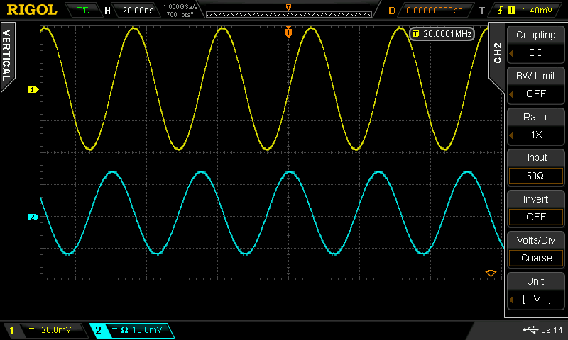
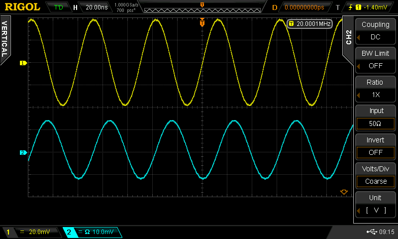
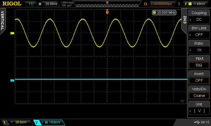
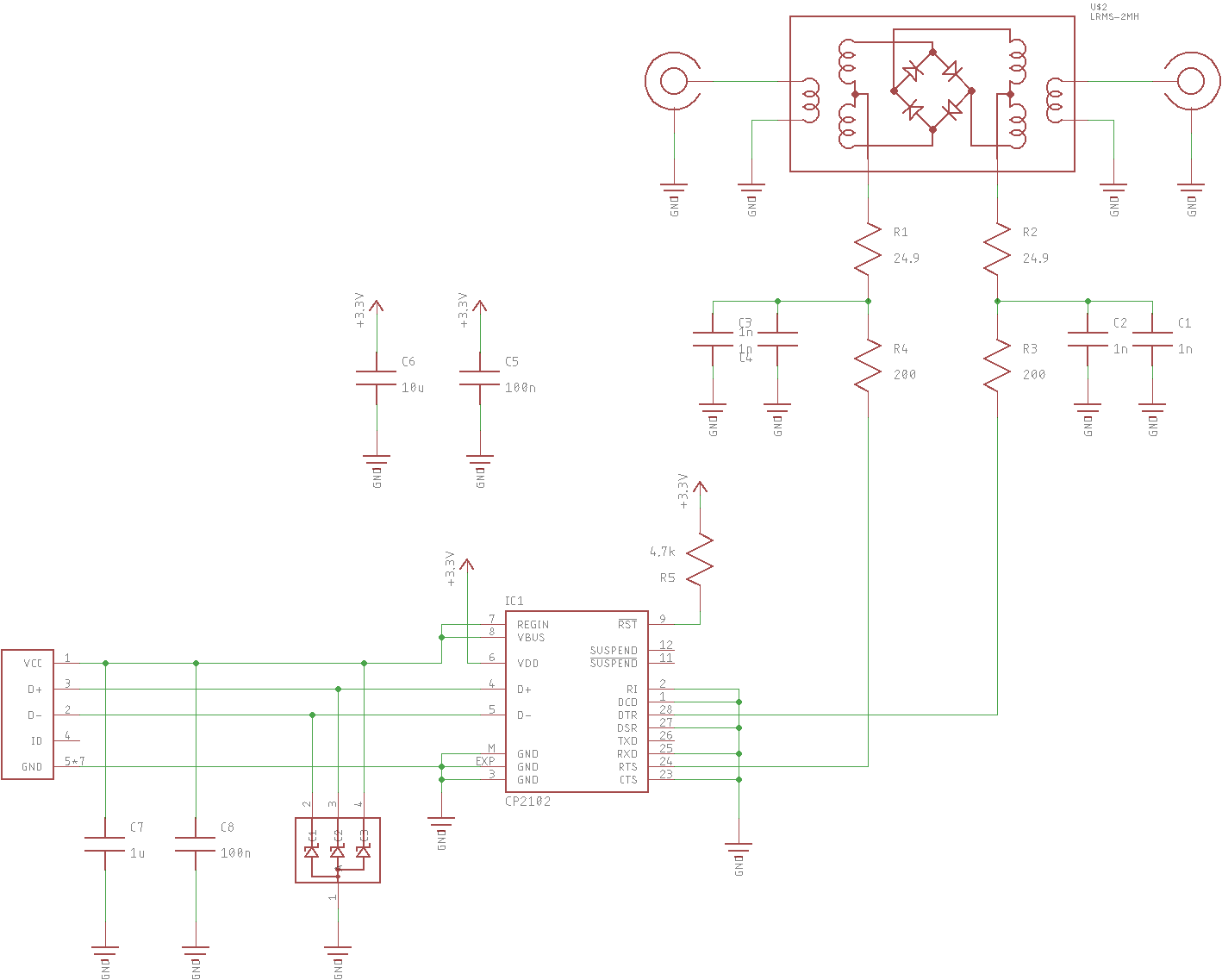
USB-Controlled RF Phase Switch

180-degrees of selectable phase

Similar projects worth following
I need a programmable RF phase switch (in-phase or 180-degrees), and this is it. It uses the RTS and DTR lines from a CP2102 USB-UART bridge to DC bias a Mini-Circuits double-balanced diode mixer to switch the phase.

Using a LRMS-2MH mixer, this should be good to around 1GHz.

I need such a thing for a continuing series of experiments on working around the limitations of the Rigol DSA815 spectrum analyzer.

I need a USB-controlled RF phase inverter.  This might be it.

  • Assembled & Tested

    Ted Yapo03/09/2018 at 02:06 2 comments

    I populated the PCB this evening.  After re-seating the CP2102 with a little hot-air, it actually works.  Somehow the QFN package is a little finicky.  Maybe my PCB footprint is bad?  Anyway, here it is, before I solder the tin shield over the RF section:

    I tested the USB connection on an old PC and through a lousy old USB hub that I don't care about.  Just in case. But nothing got fried :-(

    Since the bias for the mixer diodes comes from the signal levels on the RTS and DTR lines, I didn't even have to write any software to test it.  I fired up gtkterm and used F7/F8 to toggle the control lines.  With DTR high and RTS low, the RF output is in-phase, while with DTR low and RTS high, the output is inverted, giving a 180-degree phase shift.  Or, maybe it's the other way around - it doesn't really matter for my purposes.

    So far, I just tested it with the output of the DDS I happened to have on the bench at the time.  The 20 MHz output I used doesn't say much about the performance near 1 GHz, but at least the basics work.  Here's the input (yellow) and output (cyan) with the switch in one position:

    and in the opposite:

    There's a nice 180-degree shift between the two.

    Although I don't need it for my application, you can also disable the output by setting DTR and RTS to the same value (although I suspect setting them both low might be best).  Here's what that looks like:

    I don't know how much attenuation you really get in this case, but I'm not using it for anything anyway.

  • Schematic V1

    Ted Yapo02/22/2018 at 22:26 0 comments

    Here's the schematic.  It uses a CP2102N for USB connectivity, and ignores the serial data lines, instead just using DTR and RTS to control the switch.

    A Mini-Circuits LRMS-2MH mixer (5 - 1000 MHz) is used to selectively invert the phase of the input signal.  When DTR is high and RTS low, the output has one phase, and with DTR low and RTS high, the output is shifted 180-degrees (pi!).  In a more typical use, the IF port is driven with a single-ended input matched to 50-Ohms.  In this case, I'm driving it balanced with 24.9 Ohms in each leg.  Same thing.  The LRMS-2MH is nice in this respect, since both sides of the IF are brought out to pins.  In many mixers, one side of the IF is grounded internally.

View all 2 project logs

Enjoy this project?

Share

Discussions

Frank Siler wrote 12/29/2018 at 10:14 point

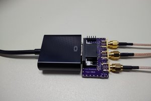
Watched your Hackaday talk- was looking for the paper you wrote.  Can you maybe attach here?  Thanks!

  Are you sure? yes | no

DN wrote 07/17/2018 at 06:30 point

i need this device.

  Are you sure? yes | no

Similar Projects

Does this project spark your interest?

Become a member to follow this project and never miss any updates