David
David-
Parts have arrived!
09/13/2015 at 18:53 • 2 commentsWith just a week to go, and two big boxes full of parts from Mouser on my bench, this week is assembly time.
On the last update, I showed off my new laser-made PCB boards, and now I have the parts to populate it. It's my first SMD design and I have to hand-solder everything as I don't have a reflow oven. So, just is case I mess up with such little time left, I have also ordered through-hole parts to make a perfboard functional prototype. The perfboard version will also be much easier to iterate on, as I use an Arduino Uno in place of a ATTINY841, which means I have enough programming space to include debugging and logging code over serial. I'm left with so little space on the 841 that I can't afford that luxury.
In parallel, I have Bst Polymerase for the wetlab experiments, to generate fluorescent sample to test my spectrofluorometer for the activated Calcien dye.
Wish me luck!
-
Laser-assisted PCB Fabrication
09/04/2015 at 20:33 • 6 commentsOne of the 2015 Hackaday Prize criteria is "“Wow” factor: is the entry innovative, is the build impressive?" Well, aside from the "Wow" of a DNA-based molecular diagnostic device, I hope this entry log is a little bit 'wow' on the build side too :)
PCB boards, stat!
Having got my (hopefully!) final schematic and PCB layout finalized, today it was time to fabricate my first PCB. Luckily, if I have messed it up, I can make new versions quickly using this technique :)
Board Preparation
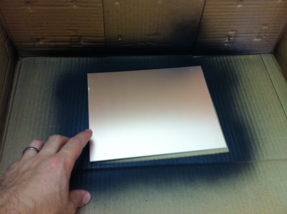
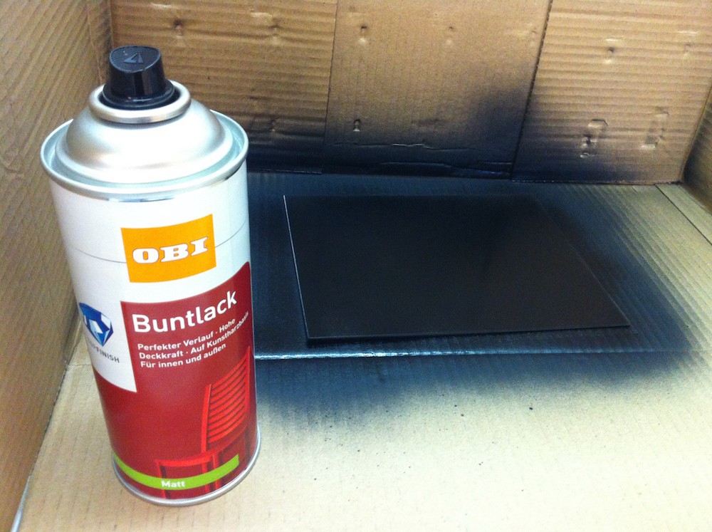
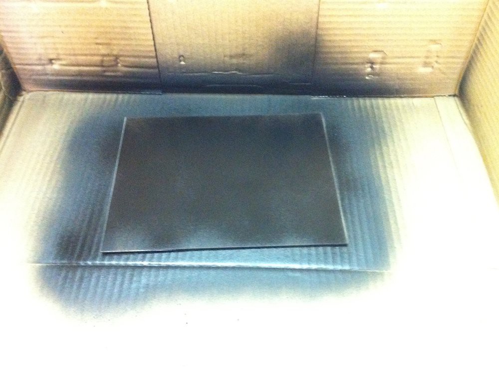
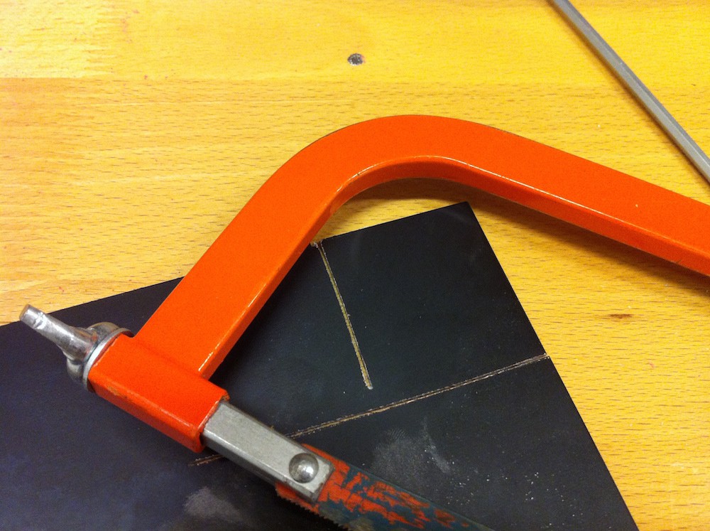
I used off-the-shelf single sided copper board. I gave them a light coat of black spray paint, waited 5 minutes, and a second light coat covered the copper I missed on the first pass. After 10 minutes, the boards were touch dry, and ready to use. I used a hacksaw to roughly cut out a section of board the right size for my design.
![]()
![]()
![]()
![]()
File Preparation
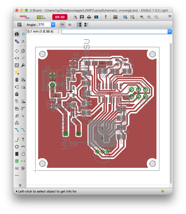
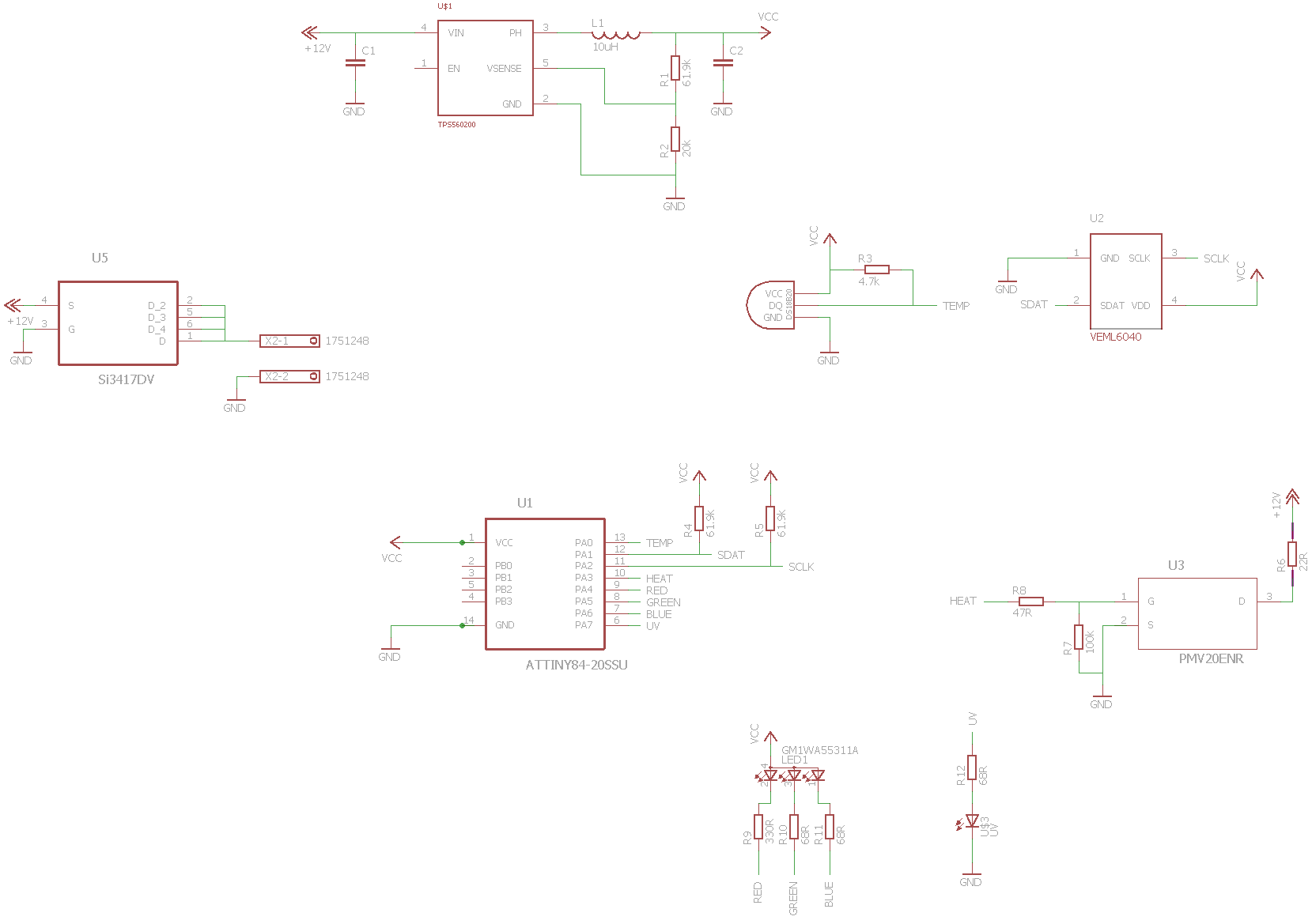
During the drying time, I prepared my PCB files. My board layout has the interface at the top, consisting of a reset and run button, and a RGB status LED. In the middle is the power input on the left, microcontroller in the middle and ISP programming port on the right. At the bottom is the heater, and the sample chamber location, marked by the grey square. Under it is the RGB sensor and UV excitation source for the fluorescent dye.
![]()
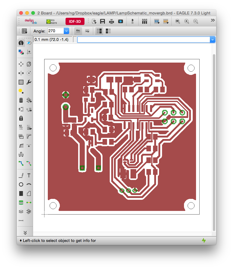
Making a PCB quickly requires just a few steps. The first is to hide all layer that should not be etched. I hide everything except for the top layer, pads and the dimension layer.
![]()
![]()
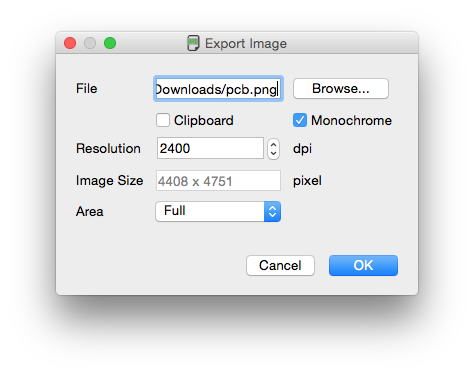
Then, I exported the image, at the highest resolution of 2400 DPI, and set the export to Monochrome. After that, use any graphics program to invert the black and white image, and you are ready to laser your boards.
![]()
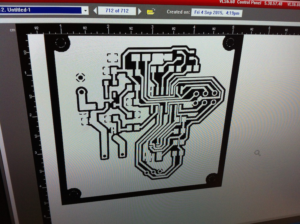
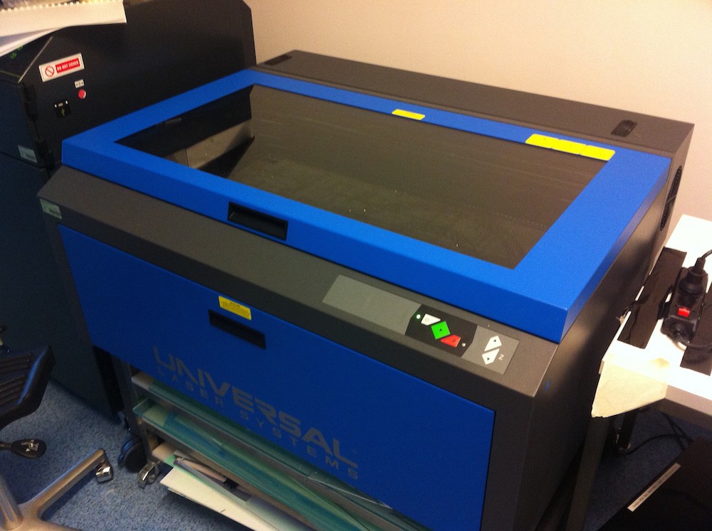
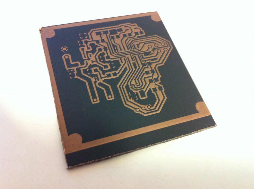
Laser Engraving
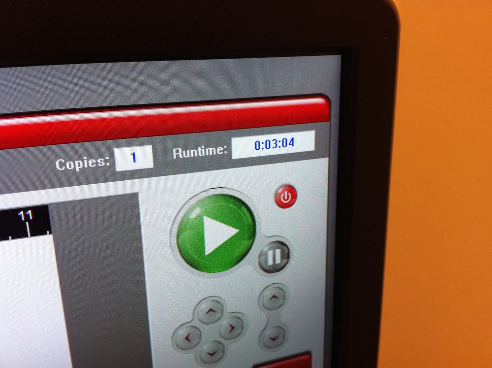
Like most CO2 laser cutters, the one I used has an "engraving mode", that can mark acrylic, anodized aluminium and wood etc. with a black and white image. A quick test found that the engraving settings for acrylic were perfect for ablating the spray paint from the copper surface, allowing the exposed copper to be etched in the next step. It's import to mention that you can't cut the copper laser directly with a regular CO2 laser system. You can do it with a expensive pulsed laser system, but you won't find one of those at your local Hacker Space. Anyway, you just place your painted PCB in the machine, load up the files with the settings for acrylic engraving, and you have your mask ready in about 3 minutes!
![]()
![]()
![]()
![]()
![]()
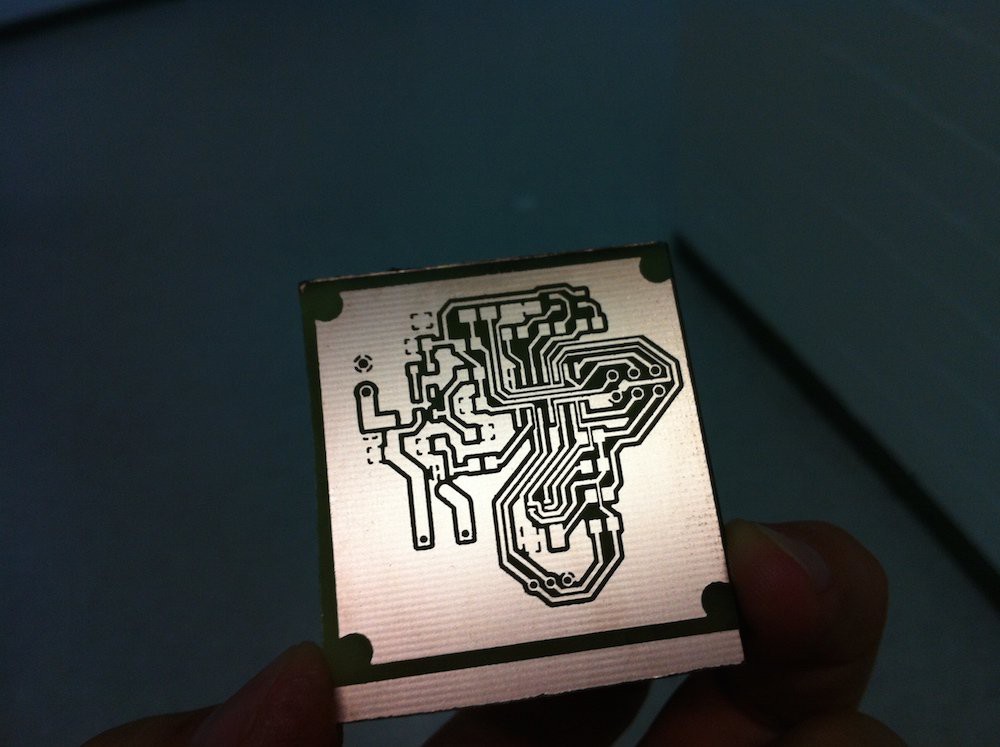
PCB Etching
After that, you do a regular PCB etching. I used a Ferric Chloride bath using the regular method you can find on google, and then removed the black spray paint mask with some solvent. Acetone removed spray paint very easily, so you won't need more than a few millilitres on some tissue paper. A quick soak and wipe, and you are finished!
![]()
![]()
![]()
![]()
![]()
If you have a few painted copper boards ready, you can go from the designs on your computer to a physical PCB board in about 5 minutes more than your etching time!
-
Initial Schematic done!
08/28/2015 at 22:34 • 0 comments![]()
-
$2 Fluorescence Spectroscopy
08/21/2015 at 14:37 • 0 commentsI just got my sensor working! This is the key element of the LAMP diagnostic device, and something I don't think has ever been done before. Digital multi-channel fluorescence spectroscopy with a sub $2 chip, The other half of the device, the precision temperature regulation system, is something I already have working in my PCR Machine. So, the main components of the diagnostic device are past the proof-of-principal phase!
A big thanks goes to Christoph on the Hacker Channel, who helped get my I2C device working!
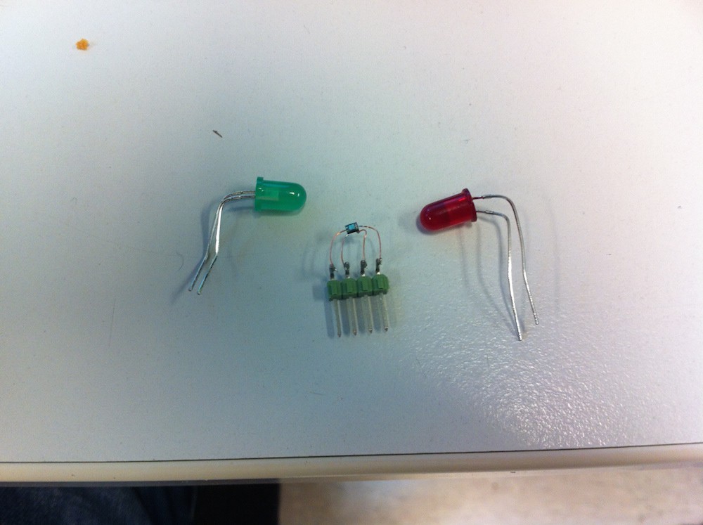
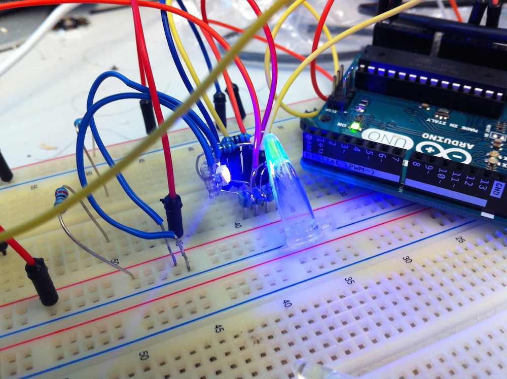
I'm using the VEML6040 RGBW color sensor, and a 405NM UV led to excite fluorescein, which had the same excitation and emission profile as Calcein, the dye I plan to use for the detector device.
![]()
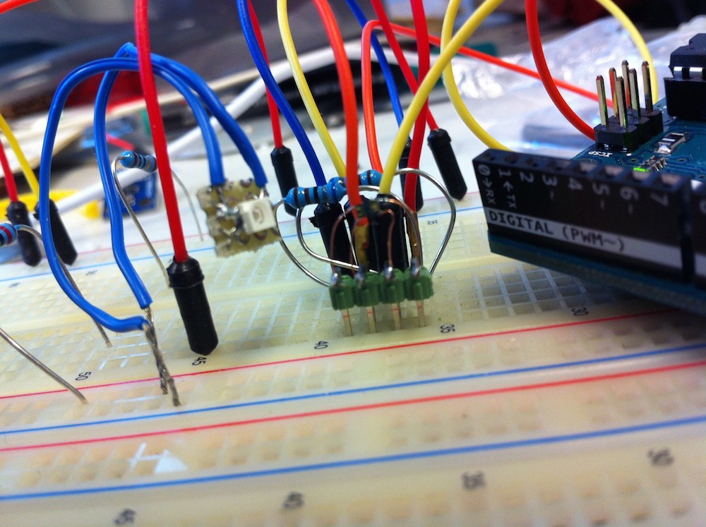
The SMD part is a tiny 4-pin device, which I have soldered onto copper wire, and then onto header pins.
The illumination is set at a 90 degree offset to the sample.
![]()
![]()
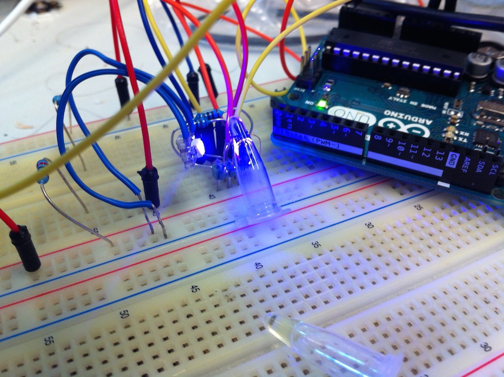
I use the UV to excite sample of water and 50 micromolar Fluorescein.
![]()
The fluorescein solution generates a bright green fluorescence, and the water none. Then if was time to record data, over the serial port from the Arduino:![]()
UV led H2O: red channel 8291 green channel 11501 blue channel 46281 white channel 65535 UV led 50um Fluorescein: red channel 11543 green channel 17613 blue channel 44271 white channel 65535 Theres a good increase in the Green channel, over 50%. Whats great, is that by using a RGB led, we can do positive and negative controls!
UV led 50um Fluorescein, lid open red channel 43481 green channel 41390 blue channel 35962 white channel 65535 UV led 50um Fluorescein, LED off red channel 311 green channel 271 blue channel 111 white channel 1208 If the UV led breaks, the blue channel drop by 99%, and if the lid is opened, the red channel goes up 500%. What that means is we can detect if there is a problem with the UV led, or if someone opens the device while the reaction is going on, both of which are vital for a diagnostic device!
Thing are going really well! I think with this key step done, I'll have the device completed in time for the 2015 competition!
-
Cheap Spectroscopy
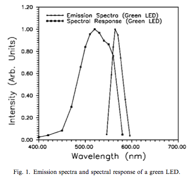
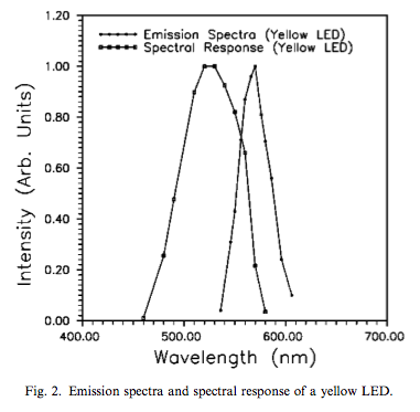
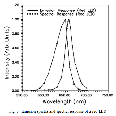
08/18/2015 at 15:56 • 0 commentsI found a nice research paper on using LEDs as wavelength specific light sensors. You can find it on google:
'Spectral and emission characteristics of LED and its application to LED-based sun-photometry'
As one might suspect, the maximum absorption wavelength is blue-shifted compared to the emission spectrum. So whats nice is that LEDs are dirt cheap, and the yellow ones are sensitive to Green light, but reject blue and UV. They might make an inexpensive sensor for my diagnostic device. I have ordered a bunch, from multiple manufacturers, and well as regular RGB detector devices. Let hope I find a cheap solution!
![]()
![]()
![]()
-
Order complete, onto testing!
08/15/2015 at 21:19 • 0 commentsOK, I went a bit overboard, and ordered about 100 euros worth of LEDs, optical sensors, temperature sensors, regulators and mosfets... Lucky I won a minor prize in last years competition!
My goals for this week are to test the best method for DNA detection, either Absorption spectroscopy are 650nm with HNB, or Calcein fluorescence. Both are tricky, when your budget is so small, and trivial with a $30,000 spectrofluorometer...
Product Detail Order Qty.
Order Qty.
price L4931CZ33-AP 5 0,851 € Pending MCP1702-3302E/TO 5 0,492 € Pending AP2204K-3.3TRG1 5 0,463 € Pending PMV20ENR 20 0,258 € Pending W7104MBC/K 5 0,624 € Pending 151053BS04500 5 0,34 € Pending TLSV5100 5 0,624 € Pending LH R974-LP-1 5 0,101 € Pending LS R976-NR-1 5 0,101 € Pending OVS5MRBCR4 5 0,467 € Pending NCT75DMR2G 5 0,606 € Pending MAX31820MCR+ 10 1,31 € Pending CLS15-22C/L213R/TR8 5 0,523 € Pending BH1745NUC-E2 10 1,22 € Pending VEML6040A3OG 5 1,96 € Pending APL3015SGC-F01 5 0,151 € Pending OVS9YBCR7 5 0,119 € Pending HT-193UY-5591 5 0,131 € Pending SML-LX15YC-RP-TR 5 0,11 € Pending LY R976-PS-36 5 0,101 € Pending SML-LXT0805AW-TR 5 0,176 € Pending SML-LX1206AW-TR 5 0,16 € Pending LA L296-P1R2-Z 5 0,171 € Pending VLMU3100-GS08 5 0,516 € Pending ISL29035IROZ-T7 5 1,72 € Pending -
Parts list
08/14/2015 at 10:00 • 0 commentsOK, I have a new design in mind. I will use Calcein as a DNA detection dye, and use a UV led and green photosensor to detect is the reaction has occured.
The parts I plan on ordering from Mouser are:
Intersil ISL29035IROZ-T7
Light to Digital Converters Integrated Digital Light Sensor
and
Vishay Semiconductors VLMU3100-GS08
405nm SMD UV LED
I was planning on using a temp sensor from Microchip, the:
Microchip Technology MCP9805T-BE/MC
Board Mount Temperature Sensors Ser output temp sensor
But Mouser doesn't have them in stock :( So now I have to find another.
-
Time to Vote!
07/29/2015 at 14:05 • 0 commentsShould I use Loop-mediated isothermal amplification (LAMP) or Helicase-dependent amplification (HDA) for the core technique? Please, post your comments and ideas!
-
Slow progress
07/29/2015 at 10:18 • 0 commentsSo, to build my first prototype, I have to build my first CNC machine, so I can machine the PCR tube-holder out of aluminium.
I have now got my spindle, and just have to mount it to my CNC framework, and model the parts in 3D etc etc etc.
DNA-LAMP Diagnostic Device
Detect HIV, Ebola, Tuberculosis and other diseases, cheaply and reliably.