 Zach Scheidegger
Before I begin, please note that this is what I would definitely consider a "hack." I did not do any balancing on the circuit, your mileage may vary doing the same project. I was not too concerned about the supply or the end device being destroyed in the process.
I started with a USB style car charger (sorry I will post some pictures of the original later), it is a basic 12v to 5v power adapter. The reason that I am using this was that it was free. I get these at work all the time when vendors come in with a bunch of SWAG. This type of adapter is usually using a buck converter because they are simple, efficient, and most of all cheap.
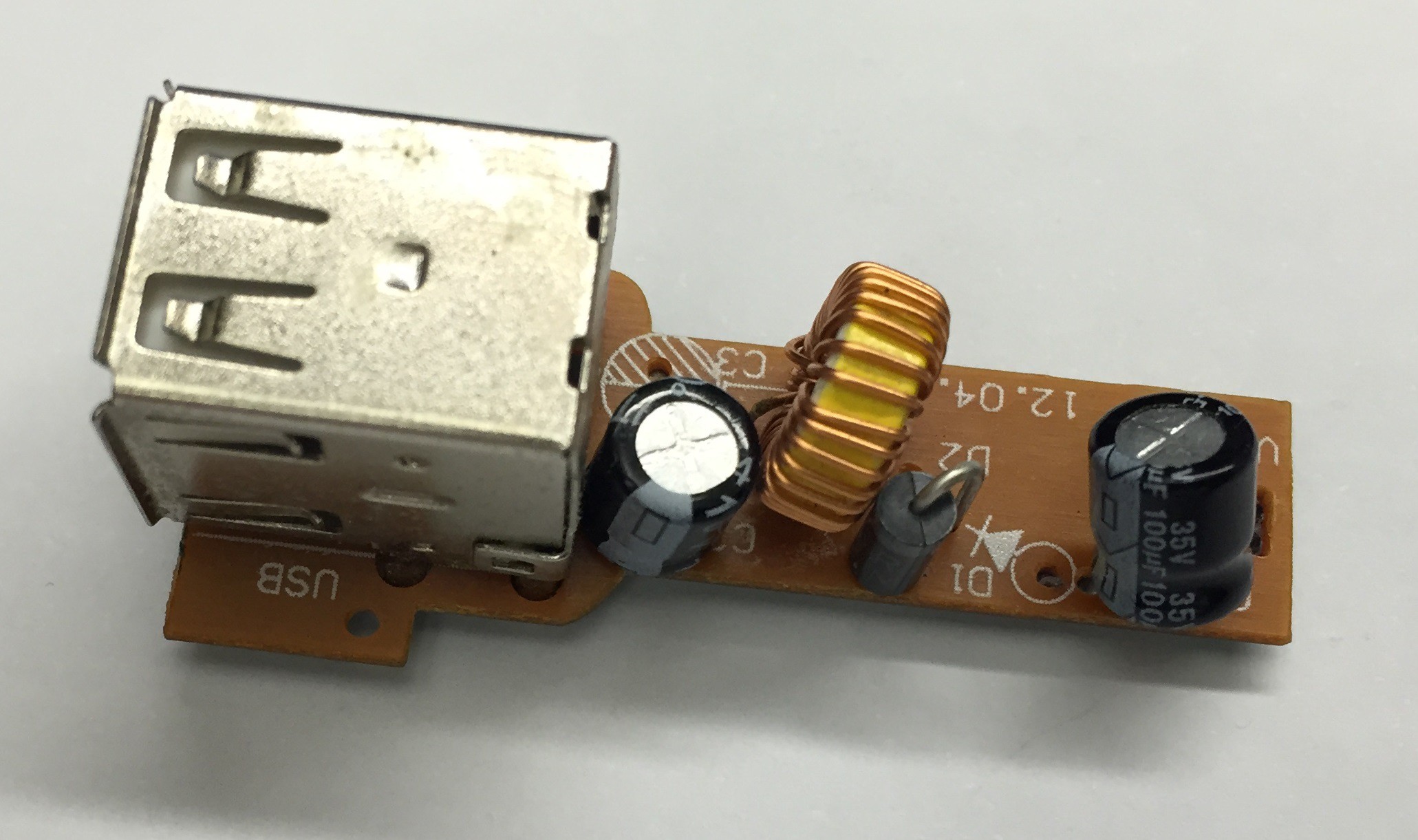
After pulling the adapter apart, here is the "top" side:
And the "bottom" side:
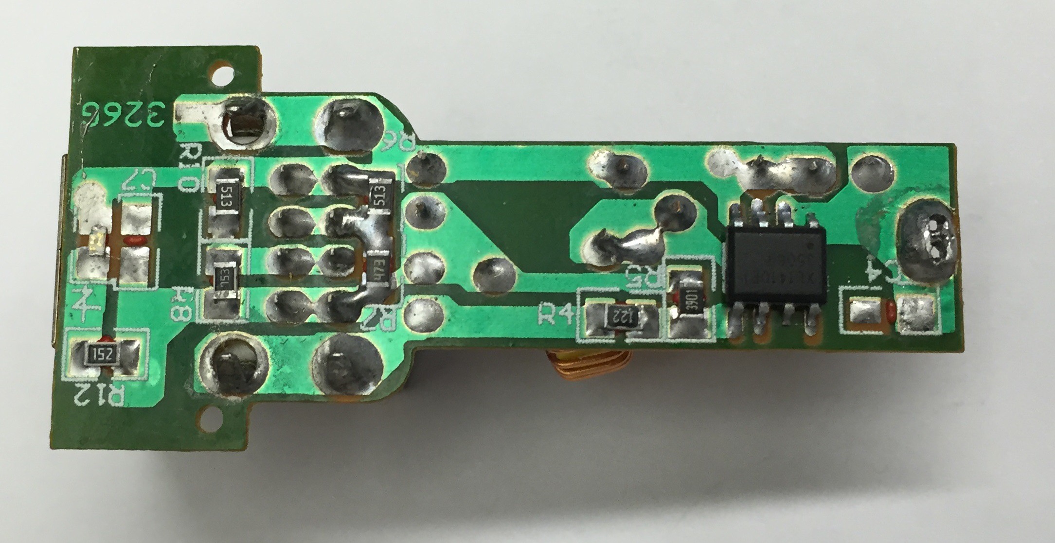
Using a good flashlight you can identify the components pretty easily:
 The buck converter is an XL1410, after a simple web search the first result was the datasheet. Looking through it you can find the basic use schematic:
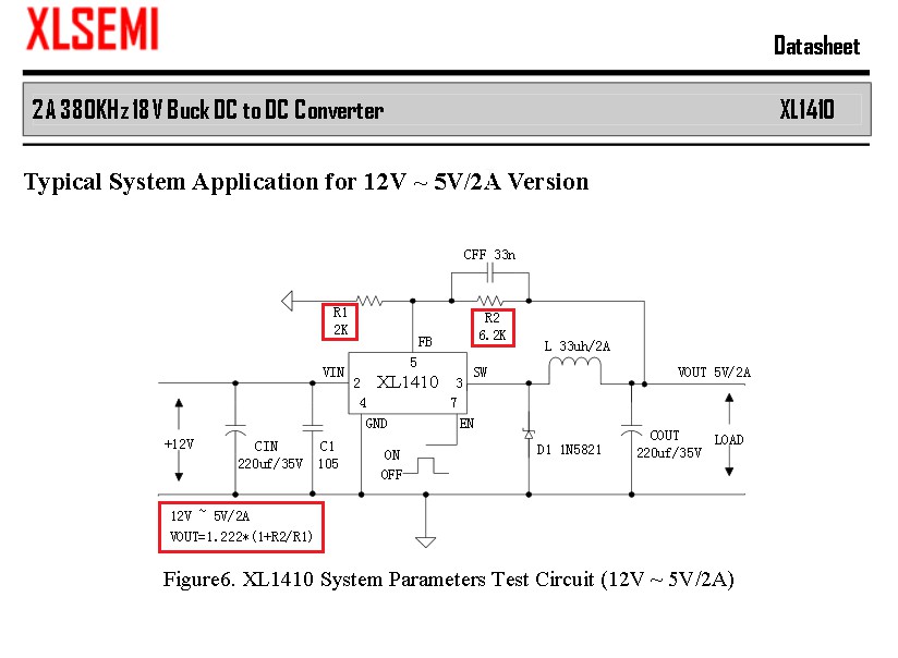
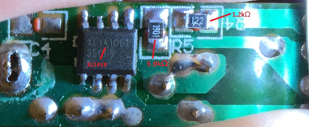
I matched up the schematic and the board and found that R1 on the schematic corresponds to R4 and R2 corresponds to R5. The designer used a value of 1.2kΩ for R1 and a value of 3.9kΩ for R2. The datasheet mentions using a value of 2kΩ at 1% for stability, but I am guessing the designer was a little more concerned on making them as cheap as possible considering they were cheap enough to give them away by the handfuls at a sales event. The formula for for finding the values of the resistors based on the voltage is the following:
So to mathematically confirm what the multimeter can already tell you:
So to change the voltage from 5v to 3.3v you have two options, or more if you are a masochist. You can replace the resistor R1 or replace R2. If we try changing R1 we will have the following equation to solve:
Solving this equation for R1 will give you a value of approximately 6.6kΩ which is way outside the recommendation for R1, and probably difficult to find anyway. Solving for R2 on the other hand will give you the following:
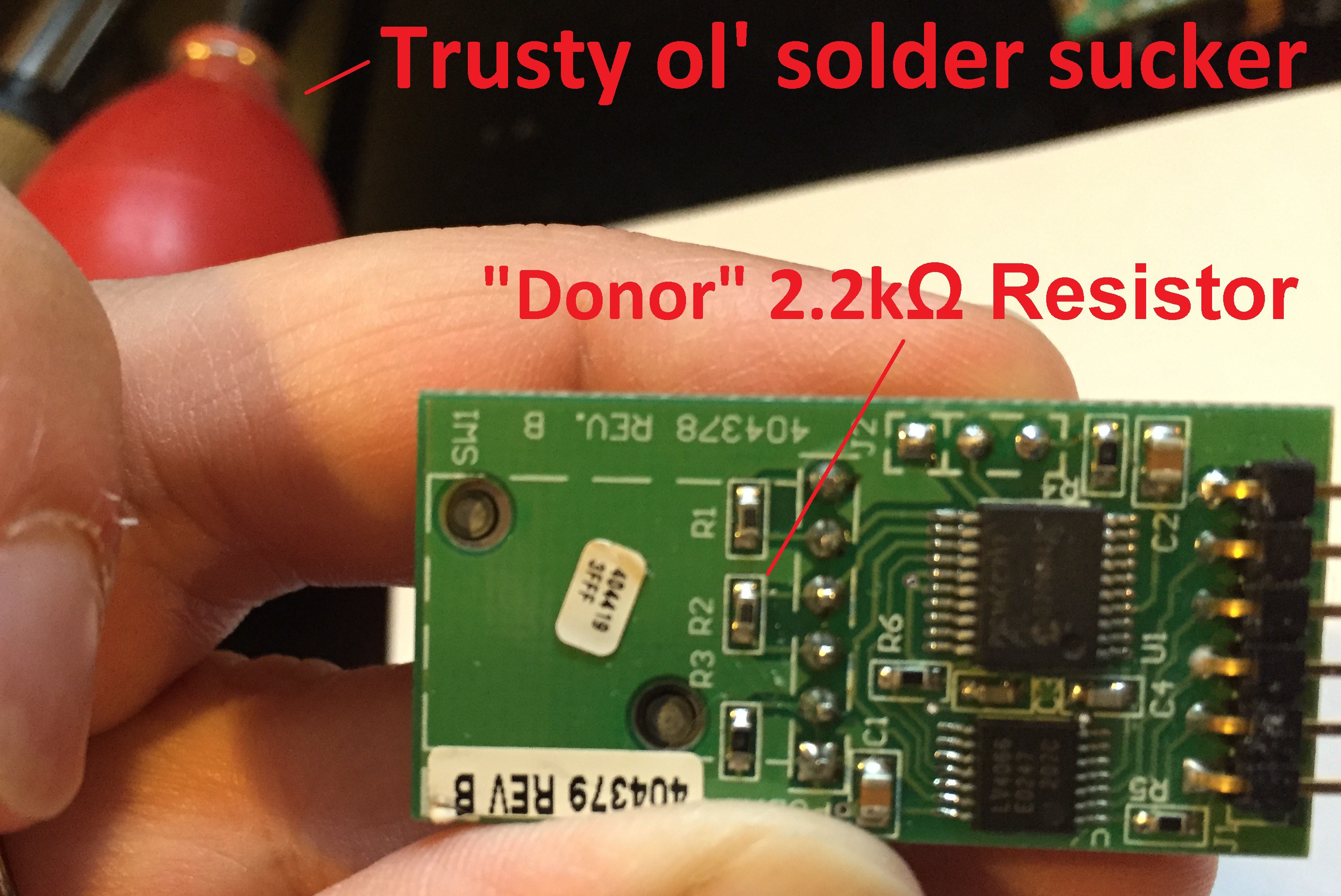
Which solves out to be approximately 2kΩ, which should be much easier to find. In fact the first board I pulled out of my junk box had a value of 2.2kΩ:
So we can solve the equation for this value in place of the original R2 value:
3.462 volts is as close as I need to be for this project. Using a solder sucker and a steady hand made removing the donor and the original resistors easy.
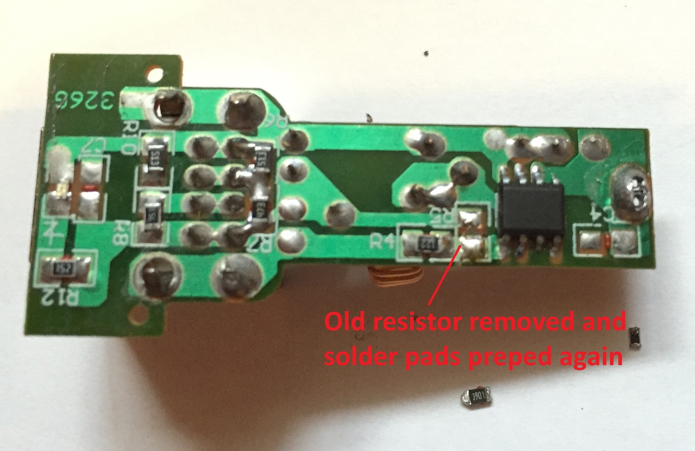
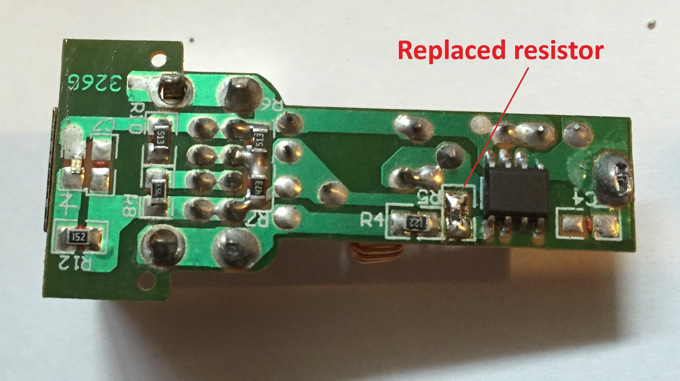
Re-tin the solder pads to make replacing the small resistor easier. Using a little solder flux and a pair of tweezers to hold it down helps too. Here is the finished product.
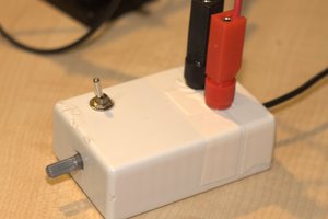
I then added a 12v supply to where the original contacts were, and tested the Vout on my multimeter.
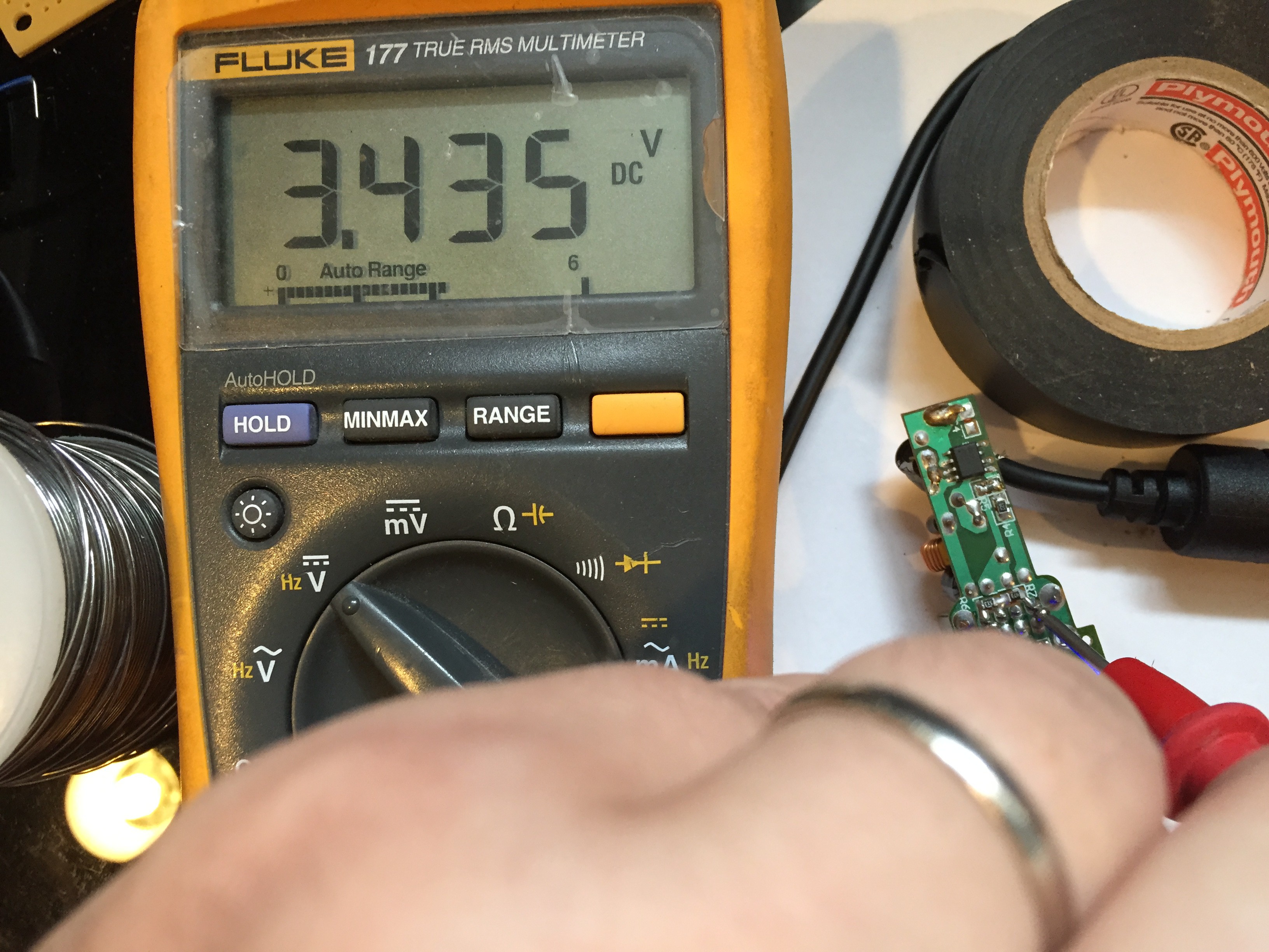
The multimeter shows an output of 3.435v. I thought this was excellent especially considering that the formula gave me 3.462v which is only a difference of only .027v, or less than 1%. The next step for me will be removing the USB output header, and circuitry on the output side of the board. Then I will do a little load testing on the board with an ESP8266 to make sure the voltage stays where I want it.
Sure, this is probably not the most accurate or balanced way to do this, but for my needs and the cost it should do what I want. Probably not much different than purchasing a cheap output supply board, plus gave me a little practice and was fun to figure it all out.


 J3TTBlack88
 Justin Scott
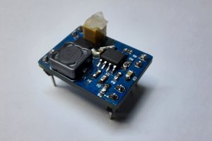
 Muhammed Esad Işık
 Savo
Savo
On the datasheet there's an example: Typical System Application for 12V ~ 3.3V/2A using R1=2K and R2=3.4K.
Why didn't you go for these values instead?