Jason Bowling
Over the last year I've been working towards an underwater sonar system for ROVs and surface boats. In order to learn the basic signal processing required to detect the echoes, I initially got a simple sonar working in air with a desktop conferencing USB speaker/mic running on Windows. A writeup, including source, is here. That article describes the algorithms used in detail and would be a good read if you want the details of how this works.
The next logical step seemed to be to get it working on a microcontroller. There are plenty of low cost ultrasonic sonar modules available that work really well in air, but the idea was to work towards getting a sonar that worked in water. There are currently no low cost sonar modules for hobby use in water. Additionally, the low cost modules only give one echo - with a signal processing approach like this, you get a series of echoes that may convey more information about the environment. As an example, a boat floating above a school of fish could detect both the fish and the bottom.
I selected a Stellaris Launchpad because of the high speed analog to digital converters (ADC) and the 32 Kof RAM. At the required sample rates, the Launchpad has just enough RAM to send a chirp, and then record a fraction of a second of audio so that the echoes can be determined. Higher frequency sound will require a higher sampling rate, so I may need to switch to a Teensy 3.1, which has 64K of RAM.
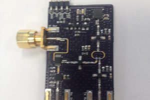
A chirp waveform is computed and sent to a small piezo speaker driven by a simple transistor circuit. The piezo supply voltage (VCC in the diagram below) is provided by 3 nine-volt batteries in series to obtain 27V.
The return echo is detected by a small amplified microphone from Adafruit. I like this module because it has an integrated level shift. Rather that swinging from -V to +V, it is shifted to 0 to +3.3V so that it can be connected to an ADC. It's very convenient.
A couple 3D printed parts hold it all to the board just to keep it pointed in the right direction.
The chirp is sent, and the audio immediately starts recording to catch the echo. The same correlation function as used in the previous article is used to pull the echoes out of the recorded audio. The intensities of the correlation function are sent through the debug port to the PC so that it can be plotted.
I need to work on optimizing the echo detection code - currently it works on the audio from each pulse for 4 seconds or so. Also, the power output of the audio transducer is very low, so range is pretty limited. It has an effective range of between 3-9 feet. Closer than 3 feet, the echo is hard to pick out of the noise produced when the pulse is sent.
As in the original experiments with the speaker/mic, the results are plotted with a simple Python program set up similarly to a fishfinder display.
Next steps are to work on getting transducers working under water and increasing transmit power. I've made a simple hydrophone to test transducers with - update coming soon.
Plans going forward:
the next challenge is how to mount the piezo element and efficiently couple the sound to the surrounding water. One way to do this appears to be to pot the transducer in a potting compound that closely matches the density of water.
This article from NOAA on building hydrophones for listening to whales details one way to pot a transducer, and also includes a high gain amplifier circuit. My current plan is to build one, and figure out how to get the ADC on the Launchpad reading the audio. From there, I can make a transmit circuit. The challenges will likely be in acoustic coupling, transducer selection, and getting enough power into the water to travel a reasonable distance.
I considered using piezo disks, but I found that getting any sort of output from them at all requires them being mounted at either their edges or nodal points in a resonant cavity known as a Helmholtz chamber. I don't think I can manufacture one to the precision needed for the small size. I'm going to...
Read more »
 MS-Dzo
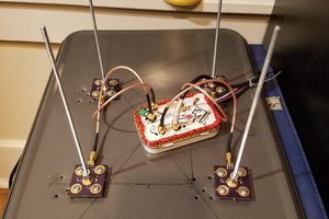
 Martin
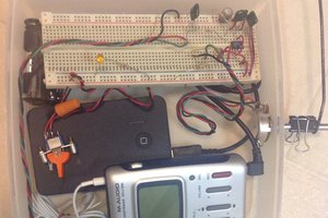
 SmokeyVW