 Lucy Fauth
Before I got the DigiPan delivered, I did some research on the internet and was rather disappointed to find nothing about this sensors at all. However I contacted a guy on a medical support forum that seemed to know about Trophy devices. As it turned out this guy had all the documents I could have wished, including pinouts and confidential powerpoint presentations. Without his help I probably wouldn't have come so far yet.
First challenge was to get the DigiPan powered. The only connection is a 8-pin DIN plug on a ~20cm long cable. Both power and data goes through this connector.
Here is the pinout of a similar type of DigiPan as mine, pinout is identical for both:

As you can see, the sensor requires 5V (2A) and +/- 15V (700mA). Also there is some hint of the type of interface this thing uses: RS422.
Unfortunately RS422 is only a specification of the physical layer, not the actual protocol. So it was still unclear how this thing sends out image data. However, RS422 is a mono-directional interface and there is no second RX channel. This means the panel can only send out data, it can't receive anything from the computer. This is nice, as this means it doesn't require any magical initialization commands or settings transmitted to it to operate normal. It works standalone, which makes it perfect for further reverse engineering
With this information I was able to power my DigiPan once I received it. Applying the 5V is enough to get the digital circuitry running. In fact there is a relais inside that only lowers the CCD and analog circuitry during exposure.
From the support manual I knew that the DigiPan sends out a test image at powerup. It is a greysgale gradient with the resolution of a typical x-ray scan.
First goal was to capture this image and display it. However, first we have to understand how this sensor actually works:
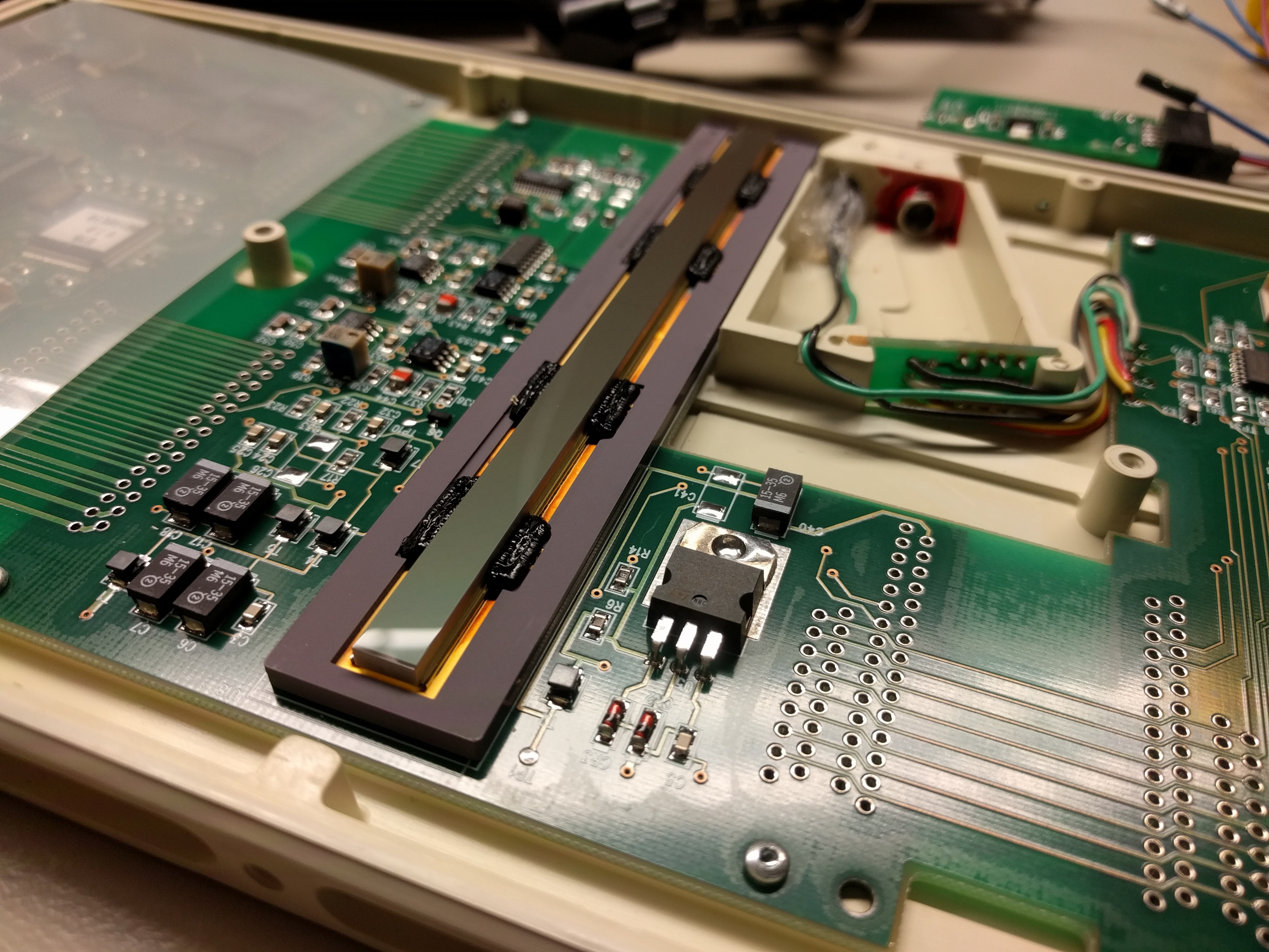
The actual CCD sensor has a resolution of 1244 x 61 pixels. While today's image sensors use a 2D image sensor with the size of the required area (up to 200 x 200mm, which is basically a whole silicon wafer as a single image sensor), this DigiPan sensor has to be slided during exposure. It is basically a 1D sensor that has to be moved to generate 2D images. From what I know, this also means maximum image witdh is unlimited as the data isn't buffered, but streamed out during exposure.
But wait, why does the sensor has 61 pixels in x direction then?
X-rays are rather weak, especially in medical context. So to get well exposed images, long exposure times are necessary. This isn't a problem for stationary 2D image sensors, but as this thing moves, long integration times would cause motion blur.
In order to achieve both high sensitivity and fast movement Trophy uses a trick called time delay integration (TDI). This works by having multiple (61) rows of elements which each shift their partial measurements to the adjacent row synchronously with the motion of the image across the array of elements.
Here you can see the data sent out by the DigiPan at powerup. Sampled with a Saleae China clone at 24MSa/s and PulseView:


Some measuring revealed a bit rate of ~7.9MHz. The crystal next to the cpu on the DigiPan pcb has 16MHz, so it's 8MHz. The protocol contains one Start bit and no Stop bit.
The actual data is 12bit + 1 control bit that seems to be always 1. The 12 bit data is the actual ADC reading of each pixel. Data is streamed out pixel by pixel, line by line, 1244x 13 bit data packets per CCD line.
This is very similar to genuine UART, however UART usually has baud rates of 9600-115200 and 8 data bits + 1 stop bit. Sigrok-cli already has an UART decoder, however only for these standard values. However adding additional options for 13 bit word length and 8Mbaud was a matter of minutes. And that is actually all it takes to decode the samples:
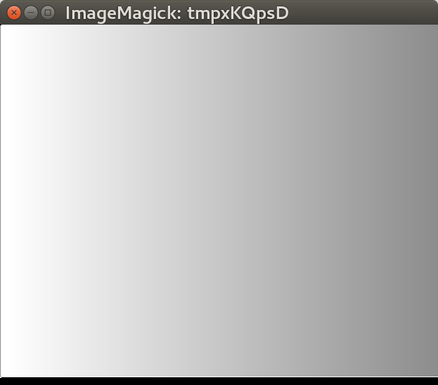
This is what the test image looks like, after being decoded by sigrok-cli and converted to a image by a 20 lines long python script using PIL.
In order to shift the pixels in the CCD with the right timing, the DigiPan needs to know the exact speed it is traveling. For this, one of the guidances on the longer sides of the DigiPans, that are originally mounted to the xray device, contains a bar code ruler. This pattern of black and white bars with a pitch of 208µm (CCD pixel pitch is 104µm) forms an optical linear encoder. Inside the DigiPan is a rather complex optical system that projects ~4 bars of this encoder ruler onto a TSL401 128 pixel CCD line sensor (red box). This sensor is read by a CPLD with a sample rate of 7.8kHz (1MHz pixel clock) which then generates the clock signals for the CCD. For this purpose, the analog signal is passed through an op-amp (green box), followed by a comparator (blue box) to generate a binary signal from which the phase can be read back.
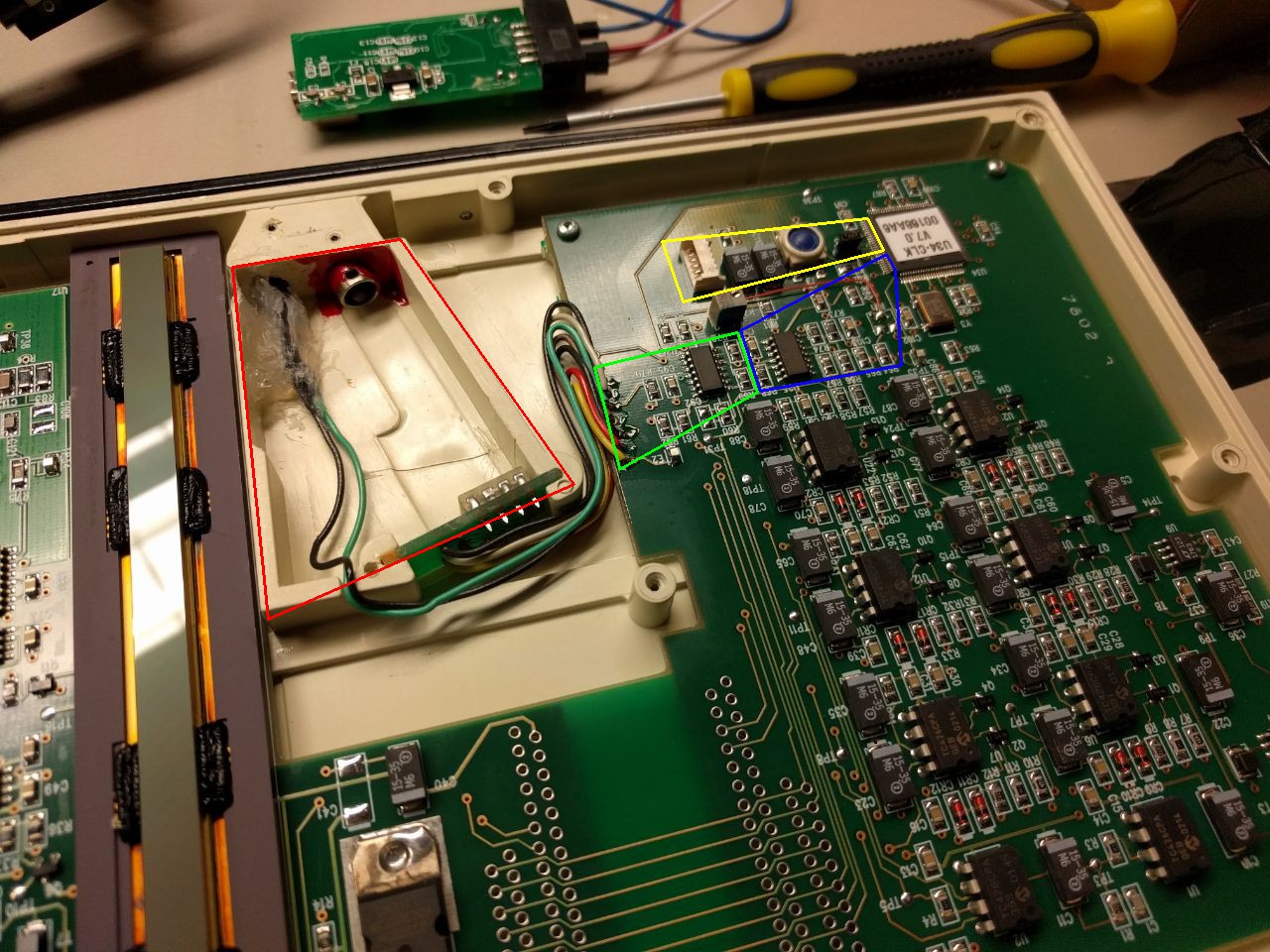
The circuit in the yellow box is used to program the CLPD.
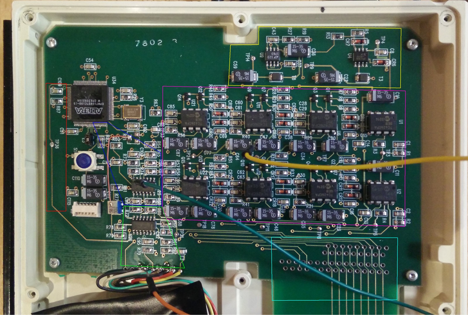
In the Image below you can see quite a few different things, in the yellow box there are two voltage regulators one which generates 10V as well as another which generates 3.3V, used by the CPLD. From the test-point in the red box, we can measure a "main clock signal" which directly coresponds to the direction and movement speed of the DigiPan. In addition to that the IC's in the purple box, which are clock- (or in some versions MOSFET-) drivers, drive directly the shift registers in the CCD's. Their input signals are also produced by the CPLD.
You might noticed the "weird" and unused footprints for e.g. pinheaders in the turquoise box. These have a matching footprint on the middle part of the PCB, the part inbetween the footprints can be removed and replaced with some flatflex cable. Thus the pcbs can be folded and stacked, which makes the panel much smaller.
It is unclear yet why it is necessary to track multiple bars and not just a single phototransistor is enough to generate the required timing. In fact, the CPLD also measures movement direction as it only outputs clock signal when slided in the director direction.
This is rather unfortunate, as one idea to use the DigiPan standalone eg. in a diy CT scanner was to replace the code ruler by a flashing Infrared LED to fake the movement timing. It is still possible to fake the clock signal, however now a STM32 is required to generate the required pattern (we will try this in a later post).
A microfocus tube is used as an X-ray source, one of which can be safely switched off and ensures good image sharpness.
We use this tube: http://m.bojin-medical.com/product/bji-2v-protable-x-ray-floroscopy-instrument-medical-manufacturer-surgical-power-tool-bji-1.html
The problem with the sharpness of X-ray images is that X-rays behave similar to light, but cannot be shaped by optics. Accordingly, a "point light source" (microfocus tube) must be used.