 Jonathan Bruneau
In a previous project log I talked about using the RT8299 buck regulator and PWMing the enable pin to simulate a MPPT. While this isn't necessarily a textbook MPPT solution, it is an appealing one due to the high level of integration and low cost offered by the RT8299.
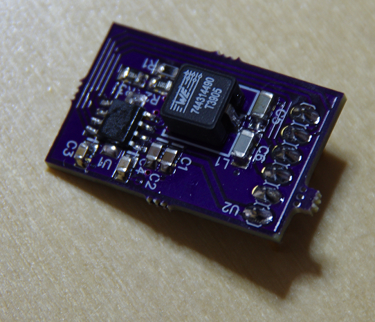
So I sent out a breakout board and stuffed it. Here it is, in all it's glory:
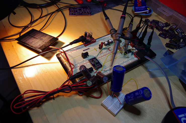
This little guy was the wired to a breadboard and then to the PWM pin of a PIC16F1705 I had handy. The input solar panel was a 5V panel lit by a lamp (playing at night requires such awful hacks) and the output of the regulator was tied to 400F 2.7V supercapacitors (nope, I didn't typo here: 400F). The extremely large capacitance acts as a giant charge sink, eliminating the effects of the output voltage on the input voltage, thus allowing me to concentrate on the input response (i.e. the MPPT portion). The proper solution this this would be to use a electronic load bank, but since I'm lacking the cash to get one, these caps will do. Here's what the whole setup looked like.
The idea of operation was simple: stop the PWM to find out the open circuit voltage of the solar panel, multiply this value by 0.8 (the MPP), and control the solar panel voltage to this point by changing the pulse width of the PWM. 100 lines of code got me there.
But before I can run an MPPT, I need to understand the step response of the RT8299 when the regulator goes from the off to the on state, and vice versa. The results were rather surprising.
Since the part has a soft-start period of 2ms, I setup the PWM period to run just around that point s.t. we never let the regulator go to full on. Doing so would drag the solar panel voltage all the way down to the undervoltage lockout (UVLO) threshold of the RT8299, nullifying all MPPT benefits.
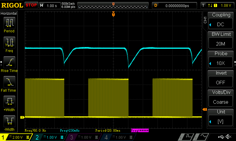
Below is a capture of the solar panel voltage (blue) in response to an on/off PWM duty cycle (yellow) of slightly less than 50%, making sure that the on time was less than 2ms.
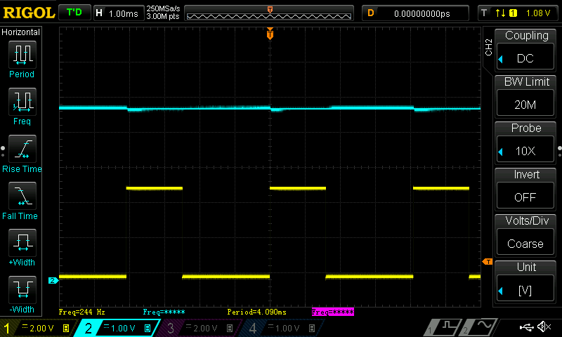
Normally I would expect the solar panel voltage to go down some as the regulator begins to energize the inductor, but it doesn't really budge. Knowing that the soft-start was 2ms, I changed the duty cycle to something slightly above 2ms.

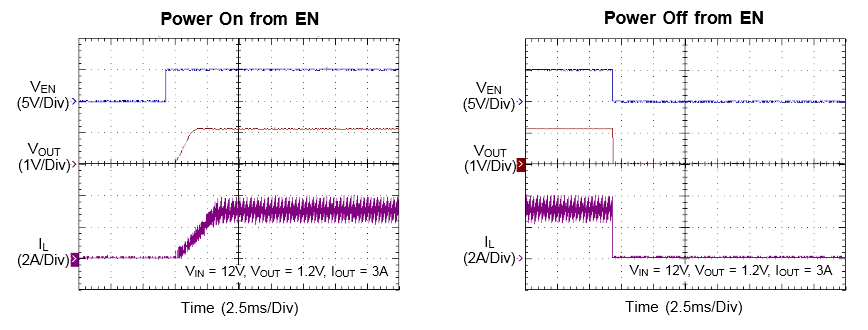
Oh my. Well, once the soft-start period is over, the regulator goes fully on as expected and drags the voltage all the way to the UVLO. So much for a soft-start. I was expecting a smooth ramp-down in solar panel voltage in the time between the enable pin goes high and the soft-start period ends. This doesn't mesh well with the datasheet, which shows a smooth current ramp-up.
It seems as if the soft-start relies on the rise in output voltage to properly operate. If so, having those 400F capacitors would explain why the soft-start isn't working well.
I then decided to add a lot (1mF) of input capacitance on the solar panel to try and hold up the voltage long enough to better understand the soft-start behavior. While it helped a little, the sharp drop in voltage was still fast and sudden. For fun, I turned on the MPPT control loop to see what would happen, and the loop gives up once the softstart period ends and suddenly brings the solar panel voltage all the way to the UVLO. The plot below shows the control loop gradually increasing the PWM duty cycle until the voltage drops, at which point the loop gives up and tries again (waiting for the solar panel voltage to stabilize at it's no-load voltage).
There's still hope of making this work, but for now I'm out of idea, so I'll temporarily put the RT8299 to rest and start working on the V2 power supply, which I've recently received the PCBs. Ideas or suggestions are welcomed.
Discussions
Become a Hackaday.io Member
Create an account to leave a comment. Already have an account? Log In.
Interesting ( maybe a converter with higher switch frequency is needed !? )
Anyway... I think you still could try dual regulation on the FB pin (sense). Meaning two diodes or-ed to the FB. One from the voltage division from output and one that "signals" when below 80% of open voltage ( similar to current limit feedback )
similar to the current limit on this
www.xlsemi.com/demo/XL4005%20demo%20board%20manual.pdf
or
http://www.fieldlines.com/index.php?topic=146685.0
http://www.fieldlines.com/index.php/topic,144628.msg977808.html?PHPSESSID=7b1ed66f3ad94d792ab33e76471e8379#msg977808
Are you sure? yes | no