 Jonathan Bruneau
In a previous project log, I did a first stab attempt at hacking the RT8299 to perform MPPT by running a PWM on the enable pin. This failed miserably.
The next obvious hack was to have the feedback pin (FB) of the RT8299 tied to the solar input. In this way, the RT8299 would regulate the solar panel's voltage (instead of the output of the regulator), in effect doing MPPT. This is easy, and there are other people who have already done this, but the trick in doing this right is to have the MCU still control and update the tracking point as time goes by (in function of temperature, irradiance, etc.), and doing so with the least number of parts.
The easy solution is to use a digital potentiometer to update the tracking point, but they don't go for super cheap. I really didn't want to add a digital potentiometer.
I was kind of stumped, until yesterday. MCUs come with a DAC, which is a form of a potentiometer packaged slightly differently. With a small tweak to the schematic, I could get the DAC to behave similarly to changing a potentiometer. My first draft at this came in the form of this simple circuit:
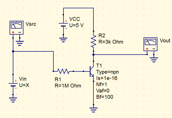
Here, Vsrc is the solar panel, Vout is the output that ties to the FB pin of the RT8299, and VCC is the supply powering the MCU. The idea is that as the voltage on the panel rises, the NPN BJT pulls an increasing amount of current, which in turn, lowers the voltage seen at Vout. Since the RT8299 regulates the FB pin to 1V, the panel will be allowed to rise in voltage until a certain voltage when Vout = 1V, which in effect, performs the MPPT.
I ran a simulation for the circuit above, and this worked out splendidly.
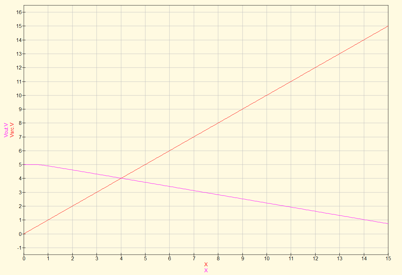
Looking at this plot, the RT8299 would keep the solar panel voltage right around 14V, which is the point upon which Vout = 1V.
Ok, so with this in mind, imagine I change VDD to, say, 2V. The voltage seen at Vout will maintain the same slope as before since the transistor will pull the same amount of current as before since it's controlled independently from the VDD voltage. On the flip side, the lower VDD voltage will start the graph (Vsrc = 0) at a lower point.
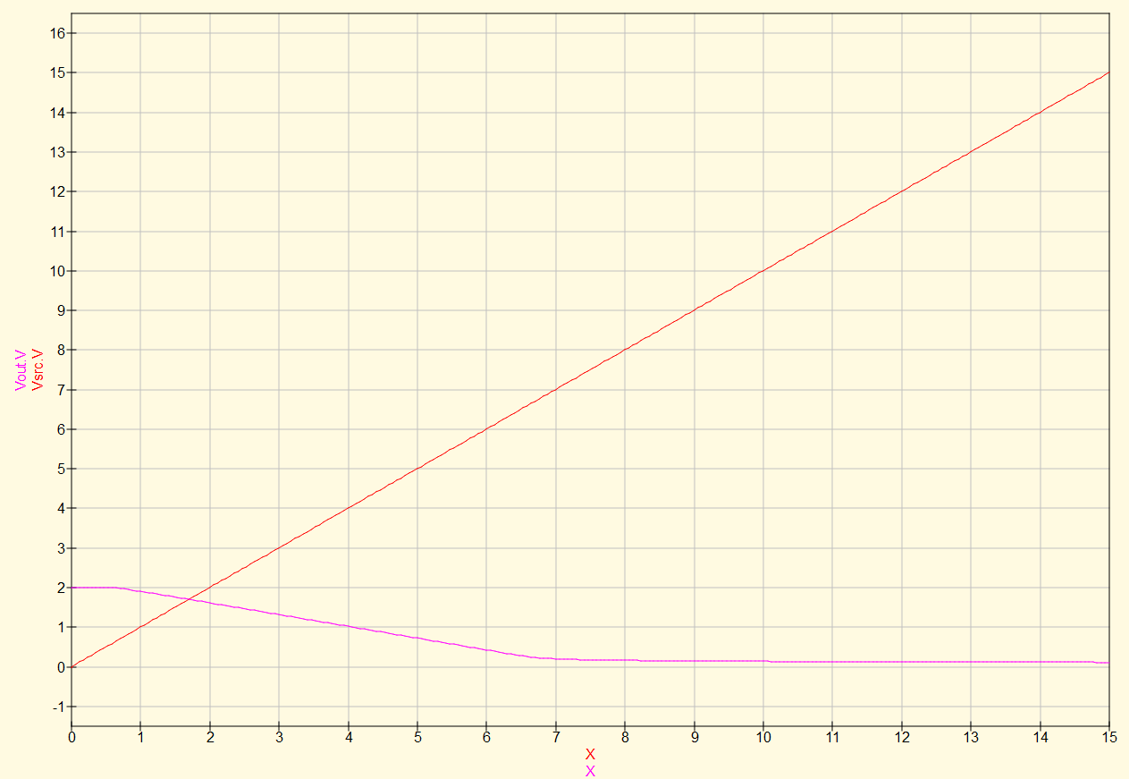
So now, the RT8299 would regulate the solar voltage to 4V. Replace VDD with the output of a DAC, and now we can control the set-point for the MPPT. Great!
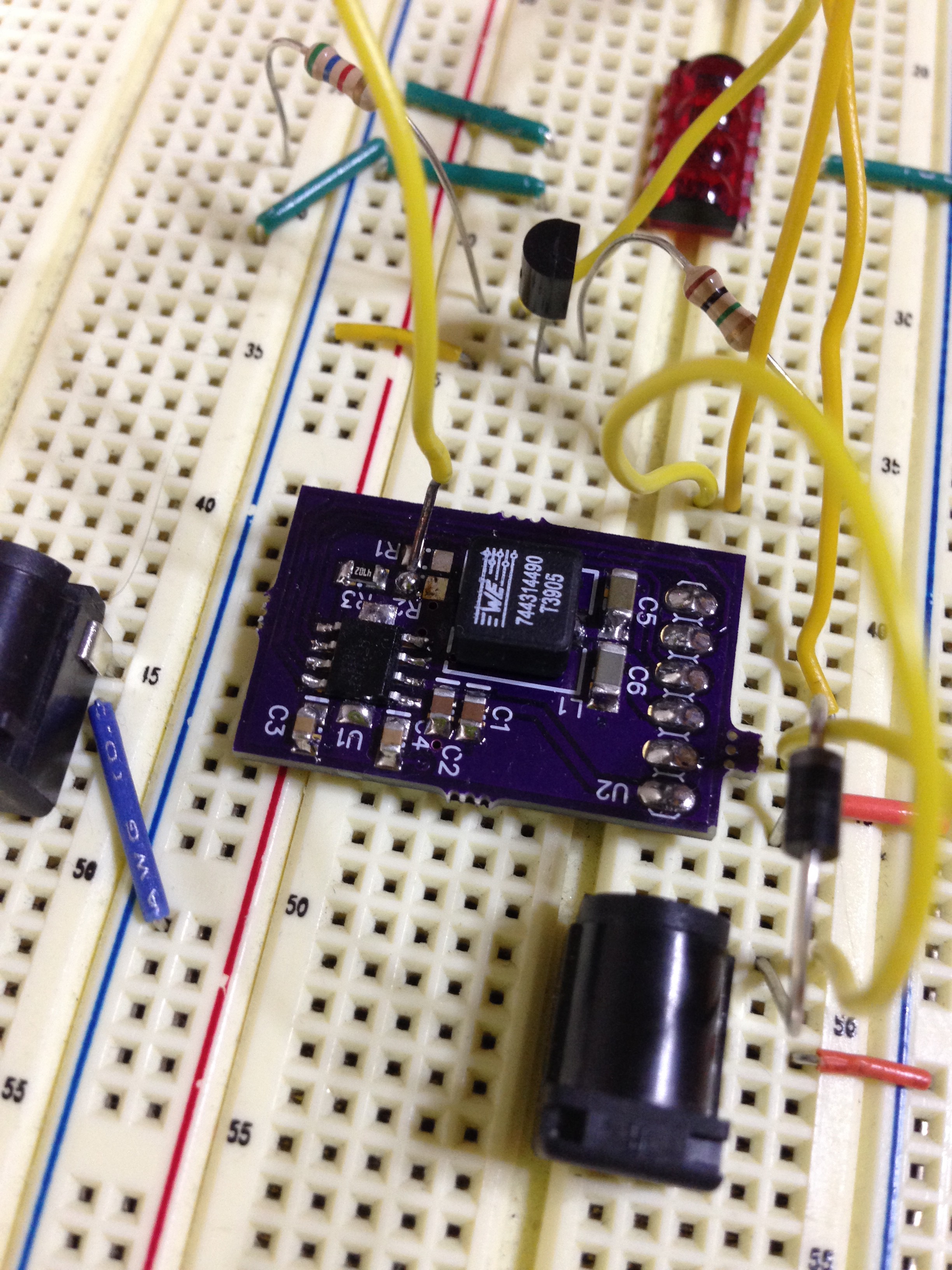
I breadboarded this, and it worked! I used a 2N2222 NPN BJT and added a wire to the RT8299 breakout board to override the FB pin. The DAC voltage came from an MCU running a simple 80% VOC MPPT algorithm.
I did have to add a unity gain amplifier to the output of the DAC to get this circuit to properly behave, and so since I need an amplifier, I dispensed of this NPN BJT craziness went with a single supply inverting OpAmp.
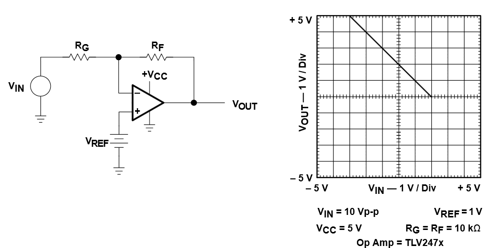
In the OpAmp circuit above, Vref is driven by the DAC output, giving the same net effect.
[BTW, I got this schematic from TI's amazing OpAmp circuit collection, which I highly encourage you grab yourself a copy (after all, it is free).]
So now the question is: how much do I care for the Buck-Boost functionality? I've looked to see if I could find a buck-boost IC for the same price as the RT8299, but no go. The advantage of the Buck-Boost is that panels of lower voltage can contribute to a higher voltage load: think 6V solar panel charging a 12V battery. On the flip side, this buck-only solution is really cheap.
I've even tried to look to find a boost converter which I could turn into a SEPIC, but the coupled/dual-inductor requirement of the SEPIC increases the cost. And forget about building a Buck-Boost out of discretes: it's more expensive than building a SEPIC.
Guess you can't have your cake and eat it too.
Discussions
Become a Hackaday.io Member
Create an account to leave a comment. Already have an account? Log In.
Nice work !!
I agree on your thoughts about boost especially for larger effects..all I've tried have misbehaved in some way.
For smaller charger solutions I've looked a bit at this
https://www.dimensionengineering.com/products/anyvolt-micro
http://www.prc68.com/I/JouleThief.shtml
My current opinion is focus on a charger that is ready to do a good job when there is "good light" > 5000 lux
https://hackaday.io/project/1936-1charger/log/12306-very-cloudy-winter-day-4300-lux-and-0-c
This probably also mean larger panels..if you need at least enough energy for a flashlight or arc lighter. And once you start to use larger panels you need a charger that can handle larger current... ;-)
My interest for a "TinyCharger" is for smaller panels on the move (backpack/cap) or similar. For stationary use I would pull out my "larger" panels ( like 20x16 cm ) and put like x3 in parallel
/JB
Using an ATtiny to control the mppt point and a small spi oled display. You could even add a current shunt and have a complete watt-meter...for a very cheap price. I would have a jumper to allow a fix mppt point in case the cpu part breaks. Graceful degradation is important
Are you sure? yes | no