 Jonathan Bruneau
It's always a good day when PCBs make it to your mailbox. There's an inner child that gets excited with the prospect of getting new toys to play with.
Two days ago was no exception. This latest batch implement the Proper RT8299 hack on a PCB (see this post for more details). Without much hesitation or interruption (minus a mandatory tea break), I soldered it all up, and it works.
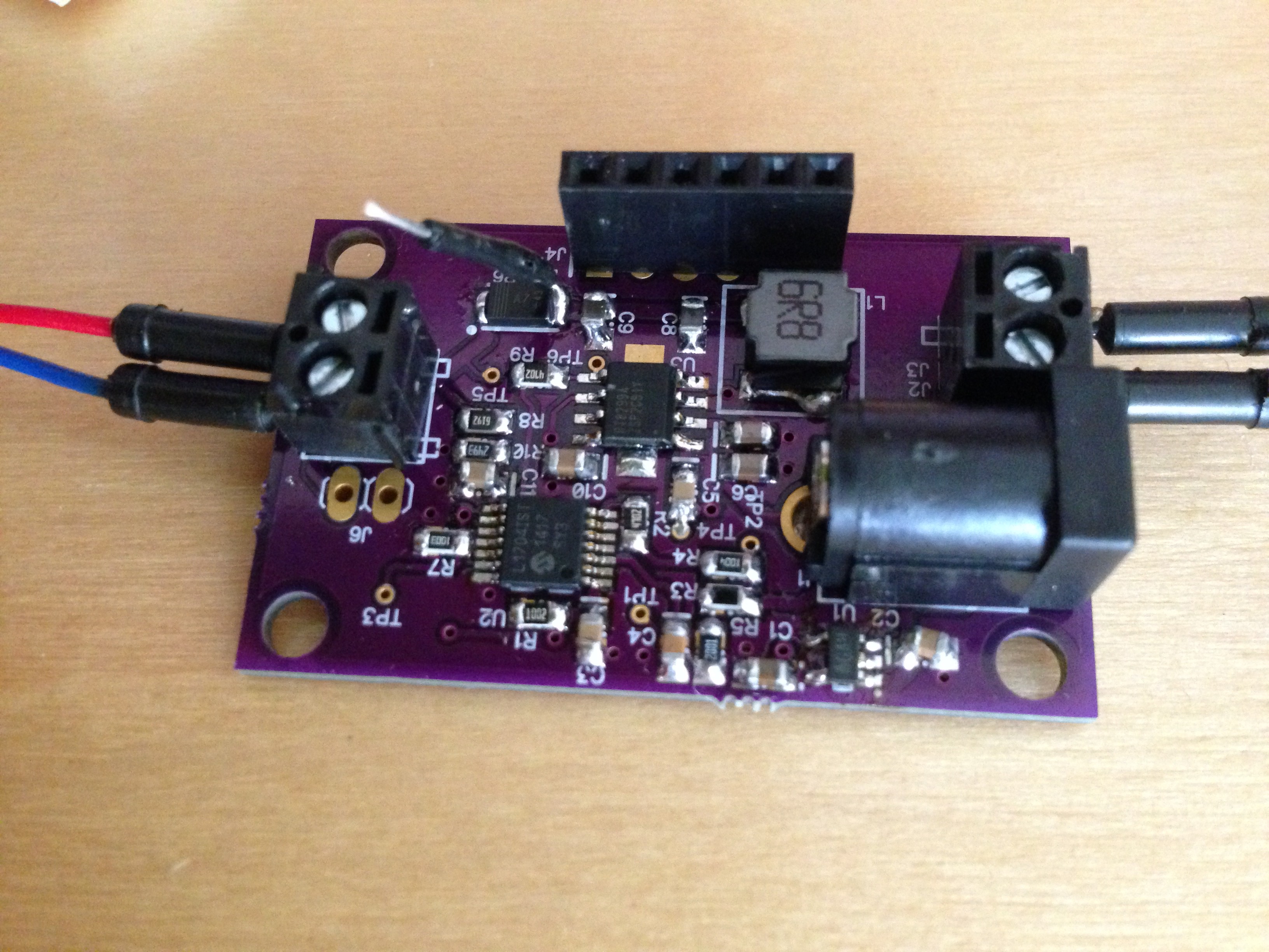
I've definitely done better soldering jobs...
Operating voltage for this MPPT is 3V-24V with a maximum current of 3A (limited by the RT8299). The total quiescent current is 1.5mA-ish at 3.3V, so 4.95mW is lost to the MCU+RT8299. I did some evil tricks on the MCU to cut down the quiescent current to 500uA, and I could get it down some more with some prodding but figured it was good enough for now.
Anyways...
Since the last post of the subject, a lot of things have changed with this design that are noteworthy
First, I opted to use the PIC16LF1704 for the MCU. It has an 2 integrated OpAmp, 2 comparators, a 10bit ADC, a 8bit DAC, and a bunch more, all for $0.75. And so, with a single component, I have all I need to trick the RT8299 to regulate the solar voltage input. I came very close to using the PIC16HV753 (same price as the PIC16LF1704) because of the MCU's integrated shunt regulator, which would remove the need for an external LDO. Truth is, the internal reference's voltage of the PIC16HC753 isn't high enough to properly trick the RT8299, so I opted to stick with the PIC16LF1704.
Ok, actually, I lied, it would work, but the reference voltage of the RT8299 and the PIC16HV753 are pretty close to one another, and I prefer having some wiggle room. It's a cost improvement that I can look into in the future, but for now, this works.
Second, I chose an inductor that had fairly decent characteristics. I could have found something cheaper, but DCR can be a large contributor to the overall efficiency, so I had to strike a balance. After lots of (painful) searching, I found the TYS60456R8M-10. With a DCR of 30mOhms and max RMS current of 3A, the $0.15 price tag seemed reasonable.
Third, I kept all the components on one side of the PCB. The idea was to allow the PCB to be directly mounted to a solar panel. Some panels offered by Sparkfun and Adafruit have really short leads coming out of the panel, so I thought why not have the MPPT mount directly on the solar panel?
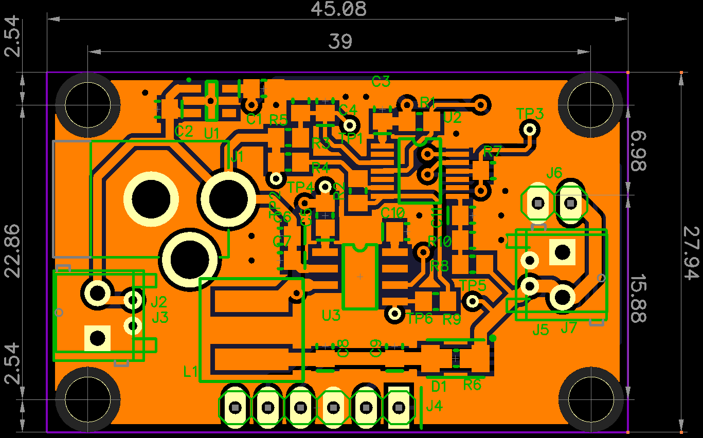
Fourth, I tried my best to get the board layed-out on 2 layers, to save on cost. This project needs to take PCB cost into consideration, so I tried. I'm not happy with the GND plane on both layers: it's cut up pretty bad which reeks to all sorts of havoc. There's some work to get it to my liking.
Here's how layer 1 look like (the big copper pour is GND, and it doesn't look to good):
And here's layer 2 (somewhat better GND, but that big fat trace in the center of the board makes me quite sad):
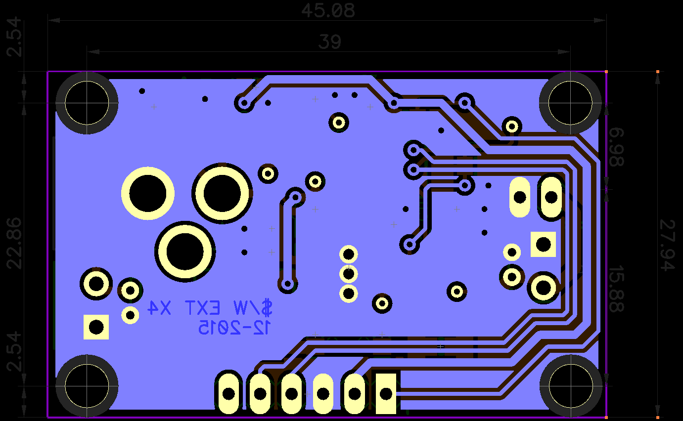 Maybe the answer is that this GND setup is a good as it's going to get, or I'll have to pony up and pay for a 4 layer board. We'll see, I need to play with it.
So, with all this said, let's see how much this board truly cost us.
This means that to get a $/W, a 6W+ solar panel would need to be connected to the MPPT board. This isn't terrible, and the boards obviously will work with much lower wattage, but the $/W will go up.
There's a few tweaks that need to happen in order to get this board completely done, but this is a great start. Another spin of the PCB and we should be in great shape.
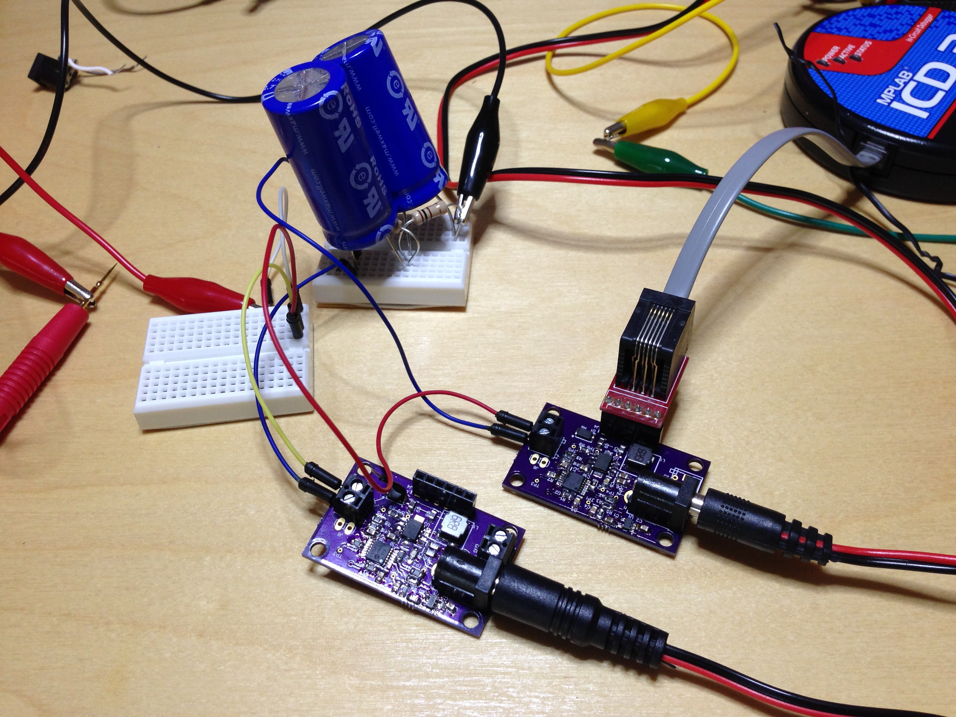
You might be wondering: what's with the diode on the Bill of Materials? Well, did I mention that these MPPT supplies are parallelize-able? Well, they are. Here I have two hooked up in parallel, both changing a super cap bank.
That's it for now. I'll post more news when I get it. Until then, happy MPPT-ing.
Discussions
Become a Hackaday.io Member
Create an account to leave a comment. Already have an account? Log In.