 Jonathan Bruneau
In a previous project log I mentioned the possibility of using the PIC12F1571 with an external OpAmp as a lower cost replacement for the PIC16F1704. It's not a huge cost savings, 20cents-ish, but it's enough to make my ears perk up.
So, I tried it.
Exact same circuit as the one prototyped in this project log, except the OpAmp is external.
It works, it runs. So mission accomplished, right?
Well no. There's an important difference between the PIC12F1571 and the PIC16F1704 that's causing the PIC12 to under perform: the Digital to Analog converter (DAC).
The DAC is used to set the MPP voltage, which the RT8299 then regulates to (see this project log with an explanation of how this works). On the PIC16, we are graced with an 8bit DAC. This gives us 256 different solar operation voltage points. That is to say, for a maximum input of 24V, we have a resolution of:
In other words, once we measure the open current voltage (Voc) of the solar panel, we can set the DAC setting to be within 0.09V of the MPP. Thats' really good.
The PIC12, on the other hand, only has a 5bit DAC, so 32 different values. For a 24V input range, this gives us:
This is sad, and for 5V panels, it's a deal breaker.
Think about it, if the Voc of the panel is 5V, the MPPT is 4V (80% of 5V). With a resolution of 0.75V, we'd either get the panel to operate at 4.75V or 3.25V. The former is barely exercising the solar panel, the later runs the board really close to the under-voltage lockout of the RT8299. Neither scenario are good. We want 4V.
This oscilloscope plot illustrates the problem quite well. It was captured while connected to a 9V solar panel, which at the time, was generating a Voc of about 8.4V. The Magenta line is the voltage of the solar panel, the yellow line should be ignored (it's the enable pin of the RT8299, which doesn't illustrated much in this case).
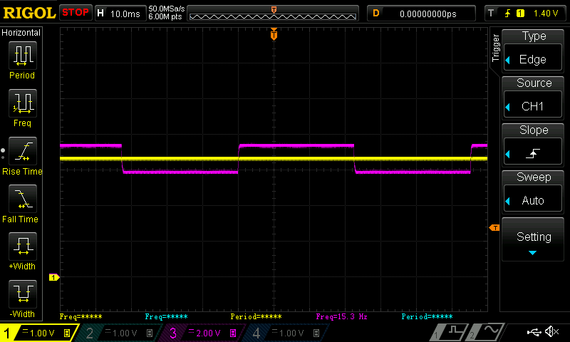
The MPPT algorithm works by first trying to guess the correct DAC value to set in order to achieve the desired MPP voltage, subsequently sets it, and then adjusts the DAC until the correct final MPP voltage is obtained (since I have an MCU I can do neat things like that). In the plot above, the MPP voltage is between two voltage points that can be set by the DAC, and so the algorithm constantly oscillates between the two voltages, never reaching the desired MPP voltage.
This longer capture shows this whole process. Again, the magenta line is the solar voltage, and the yellow line is the RT8299 enable pin.
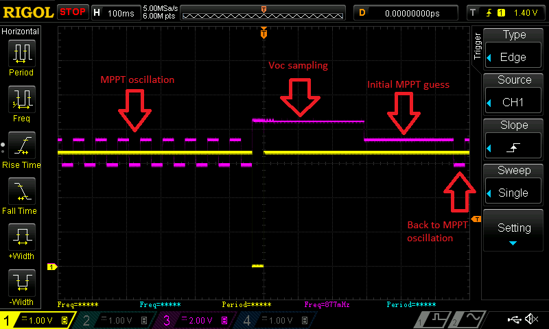
The poor PIC12: never able to reach it's goal...
So, where does this leave me? Two options:
- Try to use the PIC12F1571 awesome 16bit PWM and a LPF to generate a pseudo 8bit DAC.
- Stick with the PIC16F1704.
I can tell you that I already tried option 1, and there's quite a few problems in making it work. Two noteworthy issues: settling time and linearity, but I won't go in much more details about that. The truth is, at this point, I'm trying to do a hack of a hack, and hacks^2 never make me feel comfortable.
I might wake-up with another way to properly use the PIC12F1571, but most likely I'll just come up with more bad ideas. So I'm sticking with the PIC16F1704 for now. The next step is to redo the layout of the last board. I'll post my progress as it happens.
Until then.
Discussions
Become a Hackaday.io Member
Create an account to leave a comment. Already have an account? Log In.