 Jonathan Bruneau
Nor do we need ADCs either none.

I want a cool hat like that!
Turns out, with some clever wizardly, I figured out a way to get rid of the DAC and the ADC to make this MPPT power supply. "How and why" you may ask? Let me start with the why.
My current implementation uses the PIC16LF1704, and I'm paying a whole $0.75 for it (really, it's $0.88 because of the mandatory LDO used to power the PIC's VDD rail). And for what? A OpAmp, comparator, a ADC, and a 8bit DAC, and a really dead simple algorithm that maps a solar panel open voltage ADC reading into a DAC setting, followed by a long waiting period before turning off the RT8299 and sampling again.
Yeah, I put some fancy code to have the DAC output vary to have the MPPT output exactly track the exact MPP voltage, but that's otherwise a lot of money for something so simple. And since I'm trying to cut cost close to $1, I'm trying to find ways to take out the PIC16.
It then dawned on me that the DAC+ADC+Algorithm are not needed in order to calculate the proper Vref needed on the negative input of the OpAmp (see this log for more explanation of Vref). Instead, I could build a peak detector, and properly condition the output to act as the Vref input to the OpAmp.
In other words, instead of this (current method using internal PIC16LF1704 OpAmp):
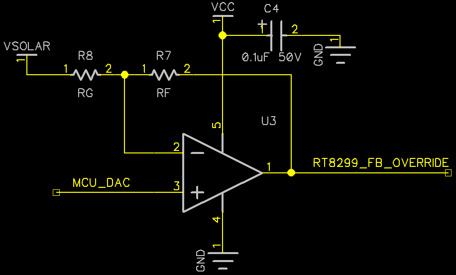

With the right combination of RT and RB, a open-circuit VSOLAR can be transformed into the same form that the DAC would normally output.
There's a nice bonus of using this MCU-less solution: I don't need to pay the cost for a LDO. There's plenty of OpAmps that can go up-to 24V for plenty cheap.
The trick, as it turns out, is timing. In order to get the open-circuit voltage of the solar panel, I need to turn the RT8299 off (i.e. set the enable pin low), and to do that, I need a timing circuit. The timer requirements are somewhat unique: it has to be a square wave with a pulse width must greater than 99%, with a period much greater than 10 seconds.
But before I got too excited, I first wired up a breadboard with the new OpAmp hookup, using me (a human) as a timer to energize the sampling capacitor C3 with the open-circuit voltage. And boy does it work.
So now I have to find a proper timing solution. I've already experimented with some timing circuits (namely the famed 555 timer), but I haven't gathered all my thoughts on it yet, so that's a story for another day.
Discussions
Become a Hackaday.io Member
Create an account to leave a comment. Already have an account? Log In.