 Jonathan Bruneau
It's a great song by the way.
As discussed in my previous project log, I was able to remove the ADC and DAC otherwise needed to perform the MPPT algorithm, vastly simplifying, if not outright eliminating the need for a microcontroller. The motivation is simple: save cost.
But there's a caveat to this plan of mine; I still need a timing circuit to briefly turn the RT8299 buck regulator off to sample the open current solar panel voltage (Voc). This is where things get interesting.
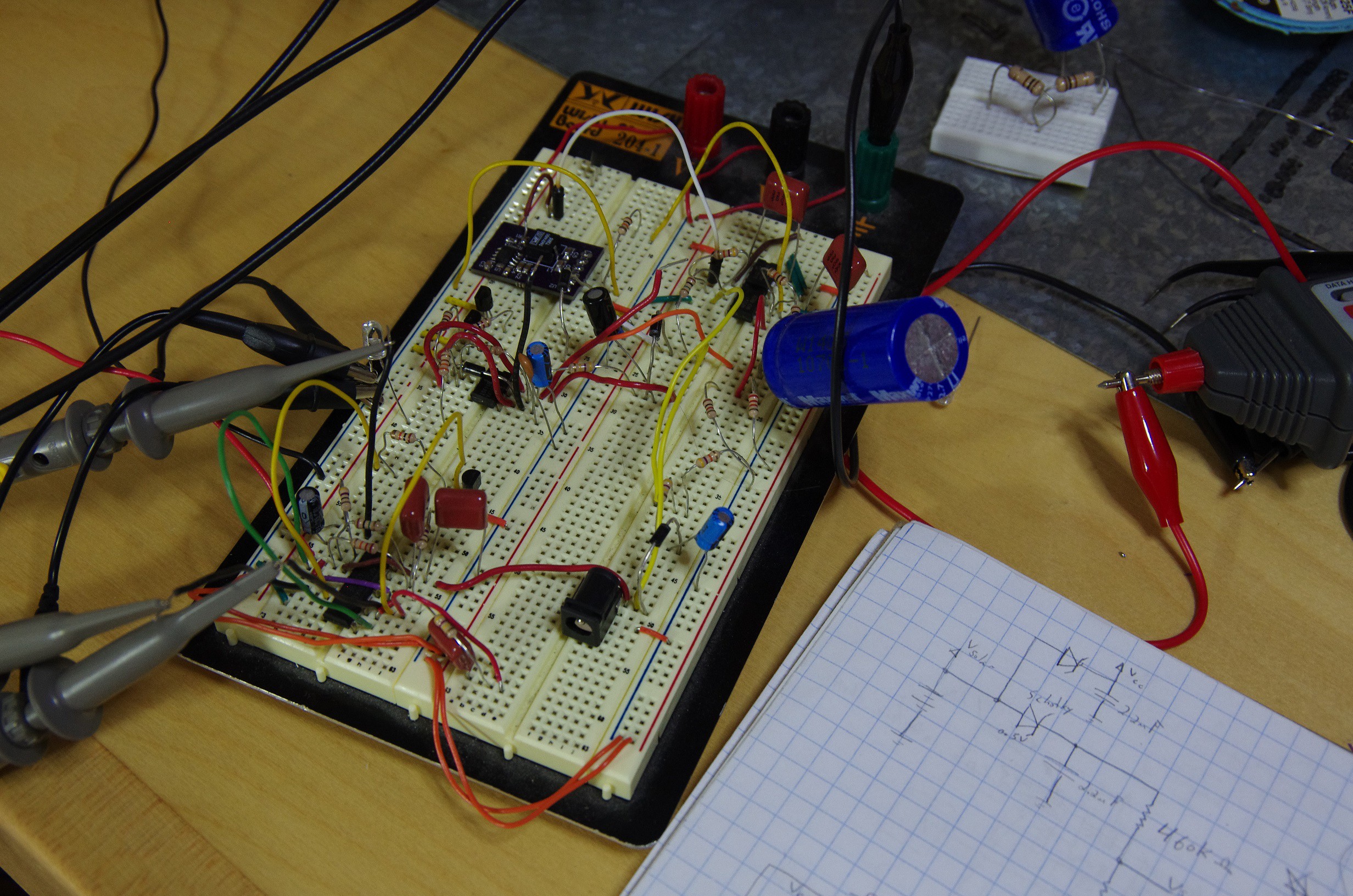
As shown by my latest breadboard, I've tried a variety of options. I'll discuss the two most interesting below.
My first inclination was to replace the MCU with the good 'ole trusty 555 timer. These ICs have been around since the dawn of semiconductor (mild exaggeration on my part), and today sells well over a billion units a year (not an exaggeration on my part). If you'd like to read more on it's fascinating history, I'd recommend this great oral interview with the inventor.
Anyways, with the 555 timer, it's relatively easy to generate a duty cycle greater than 90%. High duty cycles allows the RT8299 stay enabled and regulating the input solar voltage for as long as possible while briefly turning off to have our peak detector circuit sample for Voc voltage.
I won't go into too much details, but it turns out you can easily generate high duty cycles by using a diode to bypass the resistor between the discharge and trigger pins of the timer (circuit borrowed from this site).
Not too surprisingly, this worked, and after hooking it up to the RT8299, the latter successfully regulated the solar panel voltage.
Mission accomplished. Well, sort of.
Yes, 555 timers are cheap, but the cheap ones ain't so great. At $0.10 each for the NA555DRG4, we have a 555 timer that has:
- VCC range: 4.5V-16V
- Quiescent current: 10mA @ 16V
The voltage range isn't very wide, and the quiescent current is fairly large. Not ideal.
First, let's fix the voltage range issue. The best range I can find is 2V to 18V. It's doesn't completely encompass the 24V max supported by the RT8299, but at 18V I'm willing to compromise. For that range, we're looking at the ICM7555IBAZ-T. The quiescent of 60uA is *far* superior, but the part cost $0.27 alone, and after adding all the surrounding passive components, we're looking at $0.38, more expensive than microchip's cheapest $0.31 microcontroller (PIC10F200), which could do the same job as the 555 timer.
This is where I try to be clever (clever-er?). I remembered many moons ago learning about the 4000 series and their magical ability to operate at high voltages. Enter the CD14538: a dual mono-stable multivibrator. With a VCC range of 3V-20V (not a typo, look at the datasheet), a quiescent current of 0.08uA, and a price tag of $0.14, this deserved some attention.
Being that they are mono-stable multivibrators, I had to devise a way to retrigger each multivibrator one after the other. The first multivibrator had a long period to simulate the long duty cycle, and the second had the short period to turn the RT8299 off.
After some tweaking, and realizing that the maximum allowable period supported by the IC is 10seconds, I got it to work. Rough schematic looks like this:
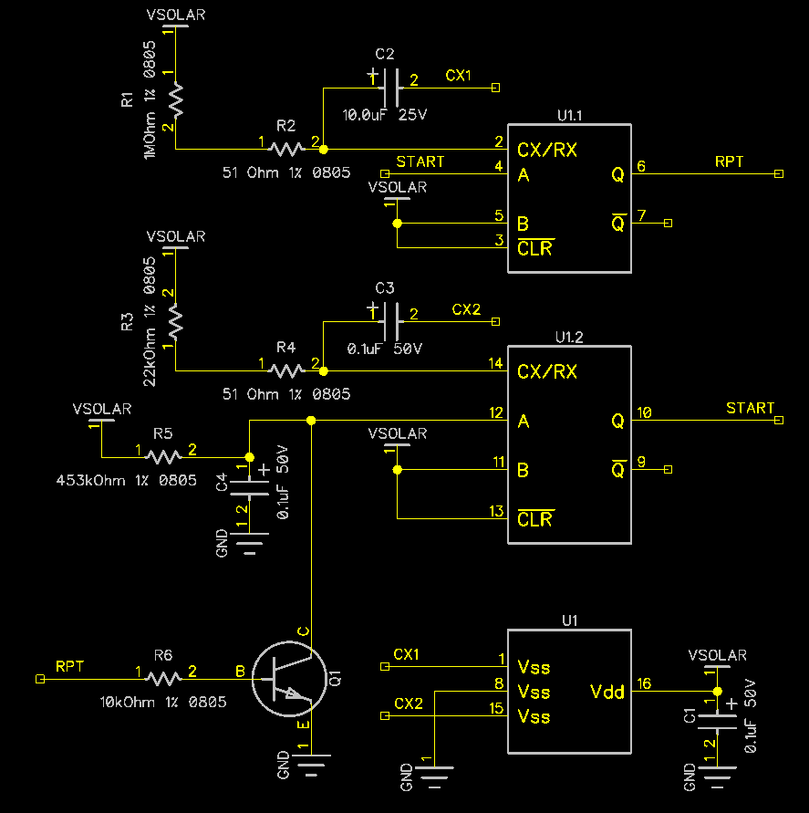
The astute observer will notice just how similar this is in implementation to the internals of a 555 timer.
As you could imagine, while a fun exercise in playing with 1970's technology, the large number of external passive add up to an impressive cost: about $0.17. Add this to the $0.14 for the IC itself, and you find that the total cost of this solution is $0.31, the same-ish price as the 555 timer or the PIC10F200. Hardly making progress here.
I'm very close to eliminating the need for a microcontroller, but this timing circuit requirement sure is getting in my way. More to come.
Discussions
Become a Hackaday.io Member
Create an account to leave a comment. Already have an account? Log In.
Have you look into astable oscillator circuits using discrete transistors for cost reduction? Only a couple of transistor, 4 resistors and 2 caps. It can work a wide voltage range.
http://www.electronics-tutorials.ws/waveforms/astable.html
You can also build oscillator using 40106 schmitt trigger or other oscillators using inverters. It is simpler circuit and you can control duty cycle by playing with the R branch by adding diodes to control charging/discharging).
http://www.electronics-tutorials.ws/waveforms/generators.html
Are you sure? yes | no
Thanks for the suggestion. I'll be playing with discrete oscillators as well as OpAmp based one and comparing results. If things go well I'll have good news soon!
Are you sure? yes | no
I like your hard work !!!
Removing the MCU and go for 80% of open voltage is a simplification ( you can't use it for TEG ) ....so why not take a step further in the same direction and use jumper or potentiometer to allow the user to set up panel-type ( 5V 9V 12V ).
Make some calculations on what difference it will make ...and compare this to what you lose anyway buy design in a buck converter ( optimal Mppt vs Fixed voltage Mppt )
Some simple measurements I made a long time ago on just a simple buck-converter and a 5V panel
The blue colored area is the power in Watt that goes in to step-down when battery voltage varies 3.1-3.4V. In this particular case 96% of "available" energy is received by the step-down. ( First you lose 80% since panel efficiency is seldom higher than 20%, then you have diode/transistor/coil losses in buck converter (10%?) and finally losses due to non optimal mppt point (5-10%) .... it might look like Pbat = Pin(sun) x 0.2 x0.9(buck) x0.9(mppt point )
In my opinion you should offer two models
1. el cheapo - reliable ( simple stupid )
2. MCU
Are you sure? yes | no
You are absolutely correct: solar panels unfortunately seldom generate much more than 20% efficiency. I know there's some recent research getting numbers closer to 40%-ish (http://optics.org/article/35465), but those panels are not yet available for mere mortals.
I like the 2-tiered model you propose, and ultimately might have to go down that path. For now I'm (perhaps naively) trying to get the best of both worlds. We'll see how that pans out.
I'm also playing with the idea of taking the concepts used on the RT8299 hack and building a buck-boost converter, similar to Linear's LTC3129 (http://www.linear.com/product/LTC3129). As you could imagine, in this kind of topology, cost quickly becomes the main issue.
We'll see. Thanks for your suggestions and for keeping up with my progress.
Are you sure? yes | no