Close
0%
0%

WiFi Camera (TimelapseMe)

Cheap wireless camera with timelapse capability

Similar projects worth following
I love timelapses! But I've found it difficult to record them. Using a phone would be possible, but then I can't use the phone ... DSLRs are also expensive and while using a cheap keychain camera from china with simple circuitry for the delay is possible, the quality of the video is horrible.

I would like to make a 720p or even 1080p timelapse camera for under $15, so you could have multiple of them on different project, all recording.

The basic idea is this:
I would use an application processor + wireless communication (Wifi or bluetooth).

A phone or tablet would set the delay for taking a picture and also for receive live video from the camera.

I would use the same camera that is in the iphone 4. It costs under 2 dollars from china and the Iphone 4 takes nice pictures.

The trickiest part would probably be processing the data from the camera and interfacing the camera with the MCU.

Similar project:

In late february 2015 I decided to change the project name to WiFi camera, since it could be used as a general wireless camera.

  • Alibaba quotes (part 2) (modules, cheapes $6 @1ku)

    Domen03/09/2016 at 20:10 0 comments

    I've received a lot of responses from alibaba for only the chips. Such a waste of my email.

    I should note that the price for RT5350 to be around $1.5 .

    The cheapest module costs $6 per piece for 1000 units.

    Read more »

  • Flashing openWRT (Success!)

    Domen03/07/2016 at 15:58 0 comments

    Michael commented today on this project. He suggested I take a look at a Russian website.

    The website (link) mentioned something about using a USB for flashing files, so I did a bit of googling.

    I found this guide.
    It's written that we first need to change the bootloader then flash the new image.


    Everything is nicely written so I won't go into detail.


    The MDT structure on the webpage does not match the on on my device. At least the bootloader structure looks ok. I'll do it anyway because I don't feel like waiting for soldering the UART pins.


    I picked the USB way because it seemed simpler.


    My USB was not at the SDA1 location, but at SDA.

    # mount /dev/sda1 /mnt
    mount: mounting /dev/sda1 on /mnt failed: No such device or address
    # mount /dev/sda /mnt
    # cd /mnt
    # ls
    uboot128.img  firmware.img
    

    I later on successfully changed the bootloader.

    # mtd_write write  /mnt/uboot128.img Bootloader
    Unlocking Bootloader ...
    Writing from /mnt/uboot128.img to Bootloader ...  [w]
    

    But when I tried to flash the firmware ...

    # mtd_write write /mnt/firmware.img Kernel_RootFS
    Could not open mtd device: Kernel_RootFS
    Can't open device for writing!
    

    Because of course I don't have the Kernel_RootFS partition as I saw before.

    So I looked at the comments and someone had the same problem.

    It seems I need to use the the 32MB RAM bootloader, but first I checked how much memory I actually have.

    # cat /proc/meminfo
    MemTotal:        28616 kB
    
    28616 / 1024 = 27.95 MB hmm wierd. Or I may have just converted this the wrong way. Anyway it's closer to 32 than to 16 so fuck it.

    At this point, I can't remount the USB drive. And because I don't want to fuck up the bootloader I'll just try the other method.

    *5 minutes later*

    Ok so now the USB isn't at /dev/sda1 but at sdb

    No need to try the other method. :D

    # mount /dev/sdb /mnt
    # ls /mnt
    uboot256.img  firmware.img
    

    Success writing bootloader.

    # mtd_write write  /mnt/uboot256.img Bootloader
    Unlocking Bootloader ...
    Writing from /mnt/uboot256.img to Bootloader ...  [w]
    

    Success writing kernel.

    # mtd_write write /mnt/firmware.img Kernel
    Unlocking Kernel ...
    Writing from /mnt/firmware.img to Kernel ...  [w]
    

    Fuck yeah.

    So that's it for today I guess.

    I'll write back to sellers on alibaba tomorow.
    I already spent 2 hours on this today and I still have school work do do. :s

    Thanks again to Michael and to the 3D Makers My embedded blog.

  • Alibaba quotes

    Domen03/07/2016 at 05:17 0 comments

    This was somewhat confusing.

    It's like they don't understand the word module sometimes, but maybe I just didn't make it clear enough (Although I did write 32MB of RAM).

    Here the supplier quoted the chip alone to be valued at $1.45, while the RT5350 module at $2.2 hmmm. I better contact him.


    See? This guy gets it. Too bad he didn't write a price. I'll just contact him.

    I'll just add more information (should have included a photo of a PCB too, but this guys are just sellers so it probably wouldn't help.


    And if you're wondering, here is my original request:

    And I also made a new request (With photo added):

    We'll see if they get it now.

  • (Almost) Flashing openWRT

    Domen03/06/2016 at 15:30 0 comments

    I looked at the instructions written here. This should be noted as the source 1 written in brackets: [1].

    "PCB marking next to the Ethernet port may be "A5-V11" or "MIFI"." Source: [1]

    On my version it's marked MIFI so that's okay.

    But just to be sure I'll check everything with telenet.

    "One can log in to stock firmware with "admin"/"admin" via telnet" Source: [1]

    I used putty.

    Default login:

    IP: 192.168.100.1
    BoC Login: admin
    Password: admin


    I first noticed the shell difference. The wiki router had msh while I have ash:

    On the openWRT wiki source [1]:

    BusyBox v1.12.1 (2013-06-20 00:48:37 HKT) built-in shell(msh)
    On my device:

    BusyBox v1.12.1 (2012-08-27 10:10:44 CST) built-in shell(ash)


    I've read here, that the ash shell is more complete then msh, and is also more configurable. Why then am I not able to list the system revision like on the wiki page [1] ?


    System revision on wiki page router, source [1]:

    > show system revision
     
      software version: 2.1.3.8
         product model: Mifi-Storage-3G
         serial number: ZJL2014XXXXX
      hardware version: 1.0
      f/w release date: Aug. 23, 2013 15:27:22

    System revision on my router[1]:

    # show system revision
    -sh: show: not found

    Maybe this command is disabled?

    It also says on thee wiki [1]:
    "If you want to access a full shell, here's how (thanks Whiterat):"

    BoC Router> cat /proc/cmdline
    Unknow command
    BoC Router> runshellcmd
    shell mode on
    BoC Router> cat /proc/cmdline
    console=ttyS1,57600n8 root=/dev/ram0

    But I couldn't follow up to the instructions. Am I supposed to connect with a serial port?

    # cat /proc/cmdline
    console=ttyS1,57600n8 root=/dev/ram0
    # runshellcmd
    -sh: runshellcmd: not found
    # cat /proc/cmdline
    console=ttyS1,57600n8 root=/dev/ram0
    

    So I looked at the info I could access in the browser:

    The software version on my device was older (2.0.04) then on the wiki page (2.1.3.8) and was released 8 months later, but the mac address did start with 2C:67:FB.

    Fuck it, I'll upload the image anyway.

    It was successfully upgraded.

    Next is says [1]:

    "Thereafter, the router is waiting for you to log in with telnet and no password via Ethernet on IP address 192.168.1.1. To access this, set your computer's IP address to 192.168.1.2 subnet 255.255.255.0."

    So I connected over cable this time.

    And I couldn't connect with 192.168.1.1.

    So I tried with 192.168.100.1

    And to my surprise, I came to the original page I saw before ... I did not upgrade successfully.

    I found a guide here.

    So I tried to upgrade the software again, this time over cable. I also used internet explorer.

    I still had no luck flashing it.

    It's a shame. After 2 hours I still haven't flashed openWRT ...

    I'll continue when I'll have more time on my hands.

    Maybe I'll even have to flash the image with TFTP ... *sight*

    Still looking for a cheaper module I could use though.

    I've found this.

    But it has an even higher price point.


    I've submitted a buying request on alibaba.


    I'll report when they come back at me with the prices.


    Today I devoted around 3 hours to this project. I think it's a good idea to write how much time I've spent on the project .

  • New idea - use a cheap $7 router (RT5350) + USB camera

    Domen02/25/2016 at 13:06 0 comments

    I decided to use a cheap 3G router from aliexpress and a cheap USB camera, claimed to work in linux.

    The router has Ralink/MediaTek RT5350F inside.

    The 3G router (link) took 23 days to arrive to Slovenia (EU). It cost only about 7 dollars.


    This is the link mentioned in the above review.


    This router is very well documented.

    The bottom two images are from that link above.


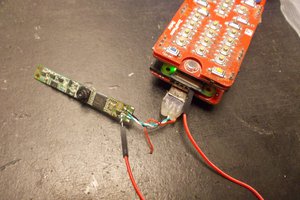
    It looks promising and it works!


    The camera (link) works too, but it's resolution is only 640x480 :(


    The image is also much closer than it actually is!

    Photo album of camera: link

    Unfortunately, while twisting the lenses to get a more focused picture, I broke something (??) and now all I can capture is this:


    Fortunately I still have a (better) linux-compatible (I think) webcam at home.


    When I'll have more time I'll install open wrt on the router and try to establish a connection with the camera.


  • Thoughts on which microcontroller to use

    Domen06/21/2015 at 21:39 0 comments

    Abstract: Atmel SAM3S + ESP8826 seems to be my best bet.

    I searched around a bit more. As I already knew, if I were to use a STM or NXP mcu, it would cost 10+ dollars for a mcu with DCMI (digital camera interface). And I would still need a chip for the BLE radio.

    Today I found out, that Atmel SAM S70 also supports a CMOS camera interface.

    It looks neat, but also simple enough to implement with the logic blocks on the PSoC. At least the SAM S70 is cheaper (about 7 dollars(at 1k units)) than the NXP or ST chips, and also in a hobbyist friendlier package.

    This webpage will also be very useful if I'll take the PSoC + camera interface with logic blocks approach. At 2.29 dollars (at 1k units) it would seem as the cheapest option, but that option comes without DMA or Universal Digital Blocks so it is useless for what I am doing. The ones that actually have the UDBs cost around 5 dollars.

    Later, I found this application note from Atmel, where they use a SAM3S4C mcu which costs only 4.6 dollars (at 1k units), which is really nice.

    And probably the best thing about it is that atmel has already written some examples with JPEG compression which is just fantastic.

    Maybe I would use WiFI instead of BLE? It seems easer to implement but more expensive to build. Than again, an ESP8826 does not cost that much.

View all 6 project logs

Enjoy this project?

Share

Discussions

miguipda wrote 03/10/2016 at 07:59 point

Hi,

I like your project to use a USB camera on a RT5350F 3G mini router with a solar power bank.

I want to use it in my garden with motion program (in motion detection) but only from 17h00 till AM 08h00. This will be used as a small hidden camera placed in a birdhouse as survey need.

But in your sample how could we choose the solar power bank (is it a 5000 mAh, more or less) needed to power this camera and be sure the wifi consumption will also be supported in the use explained here before that I want to use it. 

And in the same idea could how to choose the perfect solar power bank to power two RT5350F 3G mini router to power two opposite cameras on the same solar power bank (with two USB) ?

Sincerely thanks.

  Are you sure? yes | no

Domen wrote 03/10/2016 at 18:43 point

I'm not familiar with the energy requirements of the board so I can not currently help you. I'll go into this later, when I'll have everything else working.

  Are you sure? yes | no

Michael wrote 03/07/2016 at 08:31 point

So did you manage to install openwrt on the dongle finally? 

  Are you sure? yes | no

Domen wrote 03/07/2016 at 08:54 point

Not yet.  I'll upload the binary over TFTP this week (probably)  but first I need to solder some wires on the tiny UART pads exposed next to the enthernet port. 

I'm waiting for a friend to bring his icon nano soldering station which is far better than what I have at home. 

  Are you sure? yes | no

Michael wrote 03/07/2016 at 09:12 point

try this link I think its a way to baypass the soldering:

http://4pda.ru/forum/index.php?showtopic=377187&st=3320#entry44734190

  Are you sure? yes | no

Domen wrote 03/07/2016 at 09:52 point

Thank you :)  I'll Check it out when I come home from school. 

  Are you sure? yes | no

Domen wrote 03/07/2016 at 17:06 point

Hi again Michael. Thanks, your link helped a lot! 
Have a great day/night! :

Link to project log: https://hackaday.io/project/6287-wifi-camera-timelapseme/log/33321-flashing-openwrt-success

  Are you sure? yes | no

cmduarte wrote 03/06/2016 at 17:10 point

I would suggest buying  a broken cell phone that is still useable. Then you have everything in one camera, wifi, bluetooth. Plus software is already available.  I picked up  3 Kyocera Hydros' for about $9 each. They cannot be used on a cellular network, but are otherwise fine. Camera is 3.5Mp, plus the Hydro is water resistant so it can be mounted outdoors.

  Are you sure? yes | no

Domen wrote 03/06/2016 at 18:04 point

Thank you for you idea :) 

It has been suggested a few times, but I can't find a cheap used phone for under 20 euros where I live and shipping to my country from USA isn't cheap.


I'd really like to use Raspbery pi zero for this project but it's out of stock everywhere :(

  Are you sure? yes | no

Similar Projects

Does this project spark your interest?

Become a member to follow this project and never miss any updates