I tried connecting the camera's HDMI port to my TV to see what would happen. I used a USB port on the TV to supply power. The TV did try to enumerate the camera via USB but didn't recognize it. So it looks like the USB port is for more than just power.
On the HDMI link, it looks like a device was recognized. I don't know if it's running HDCP or not, but I did get info about the resolution and refresh rate, but no picture.
So my guess is that the camera needs the USB connection ad a control channel and not just for power. I'll have to poke at it with a PC, or see if I can l take the setup to work and use a hardware USB protocol analyzer to monitor traffic between the set top box and camera.
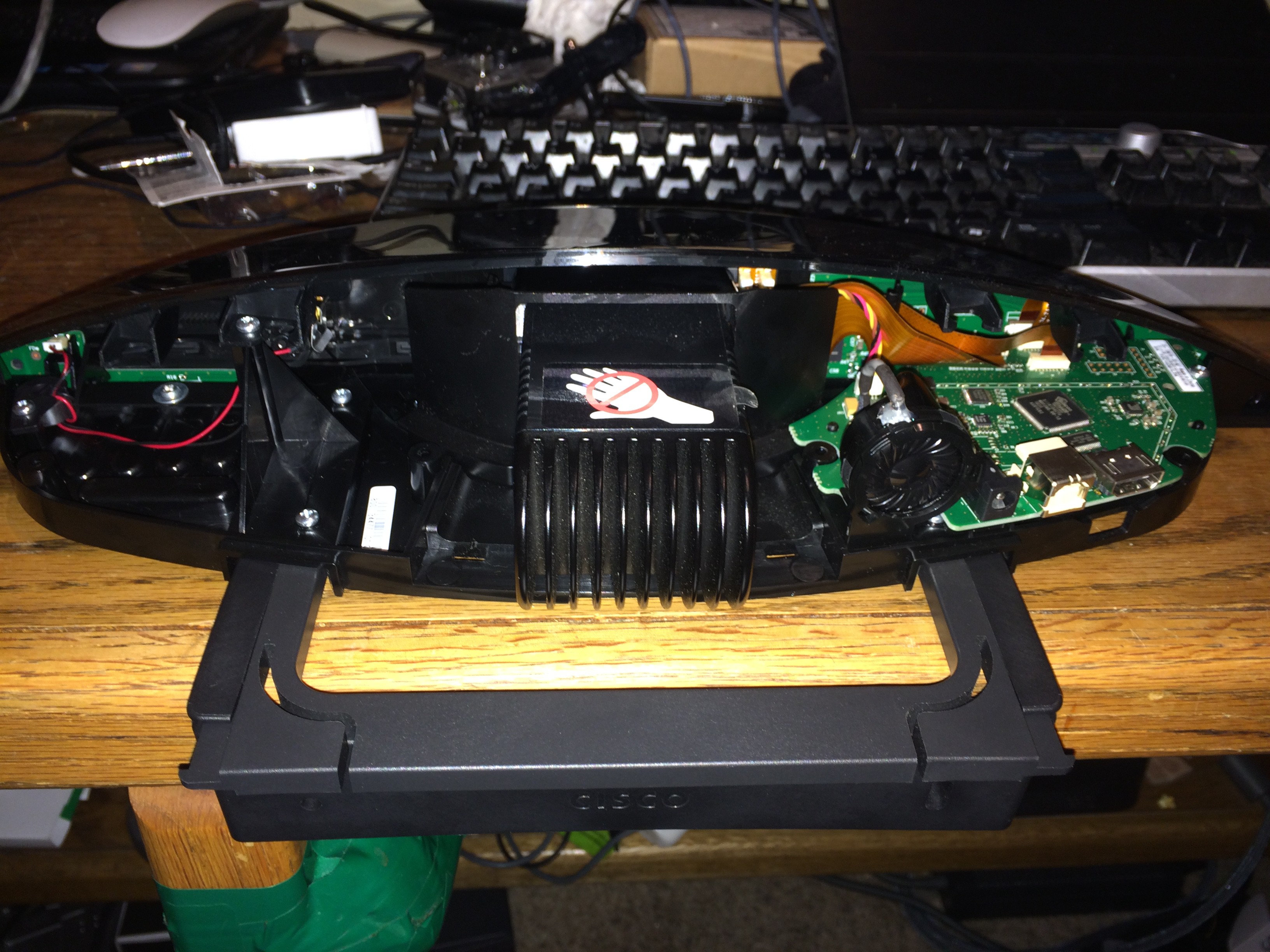
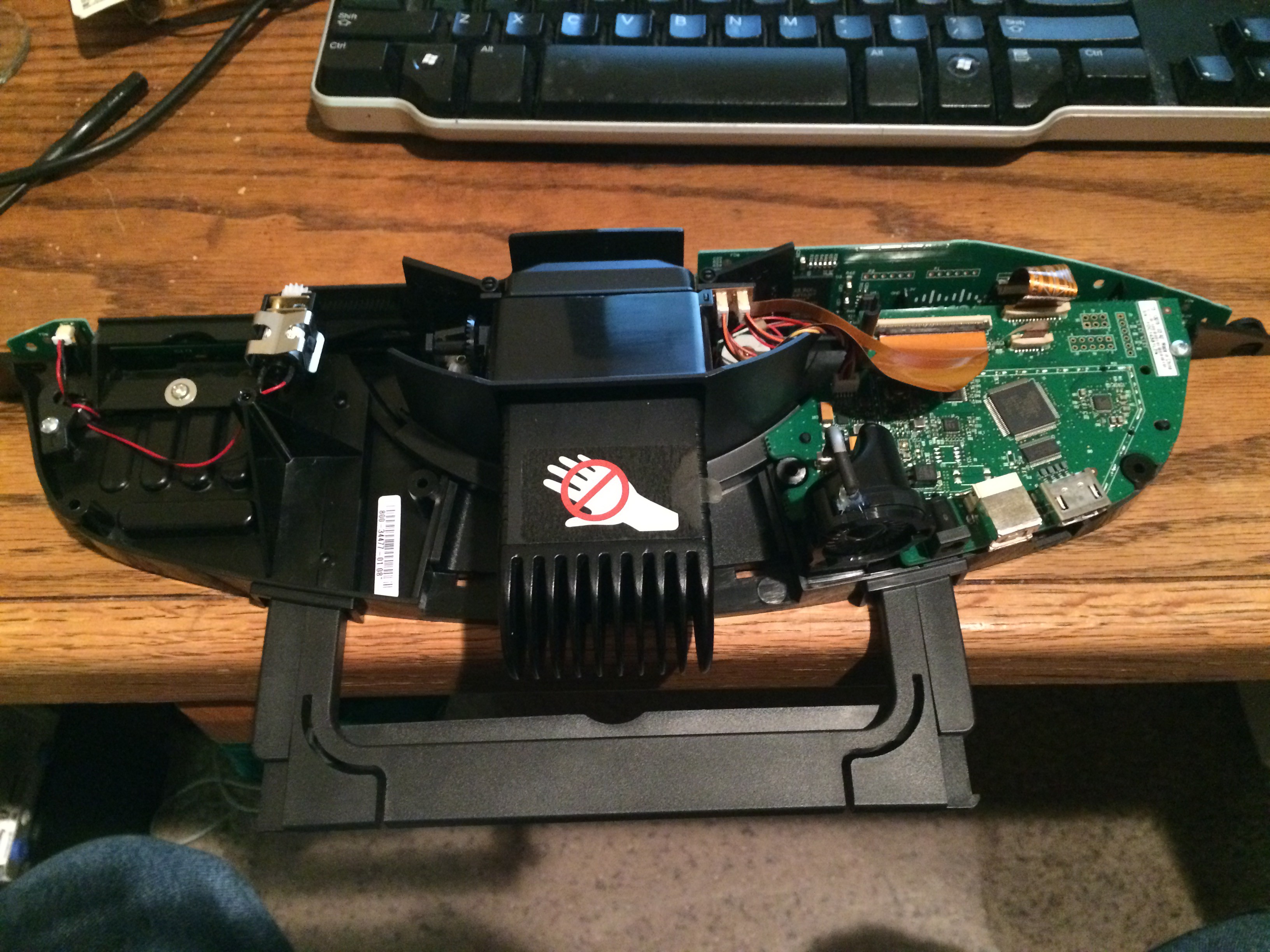
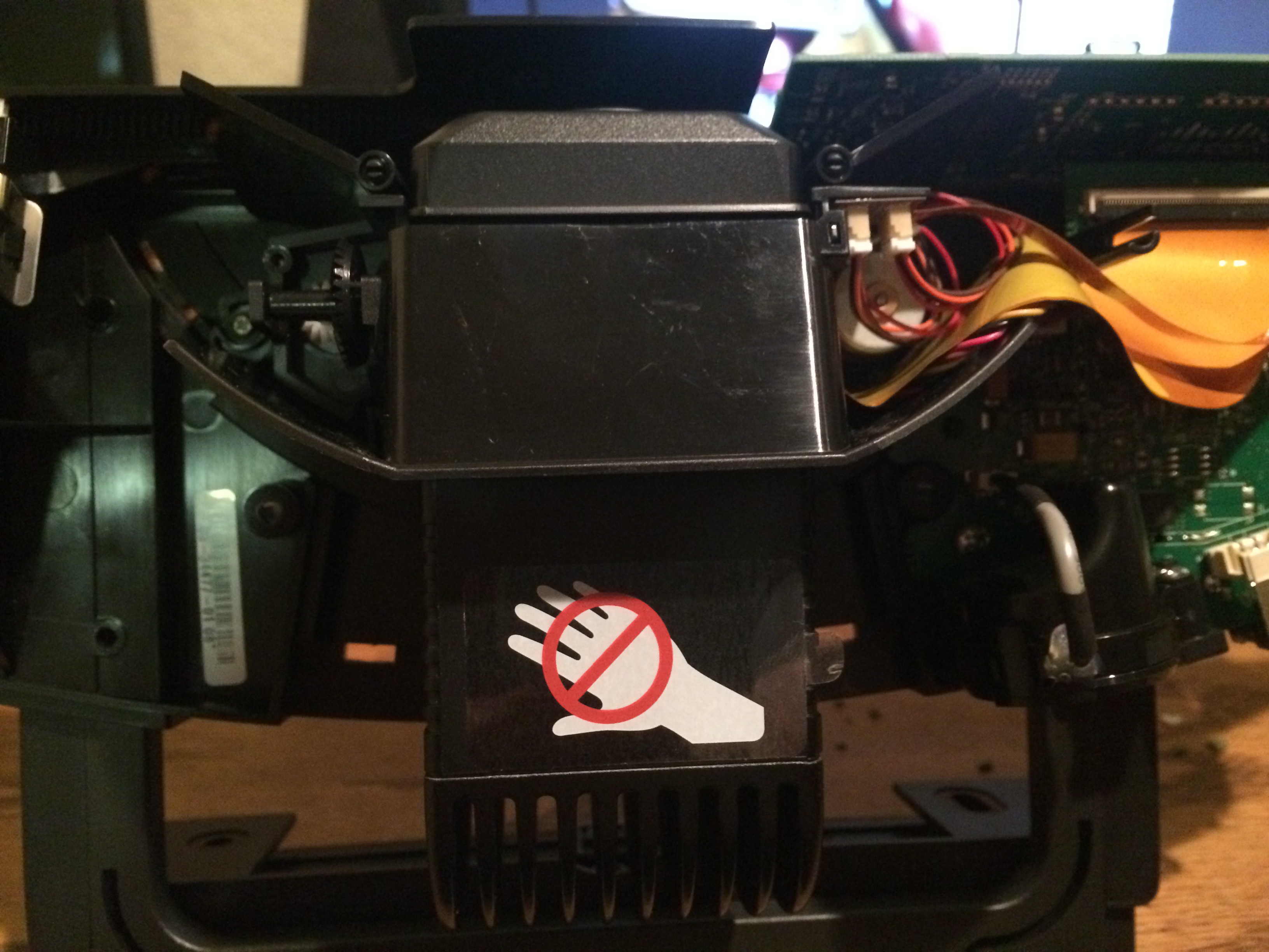
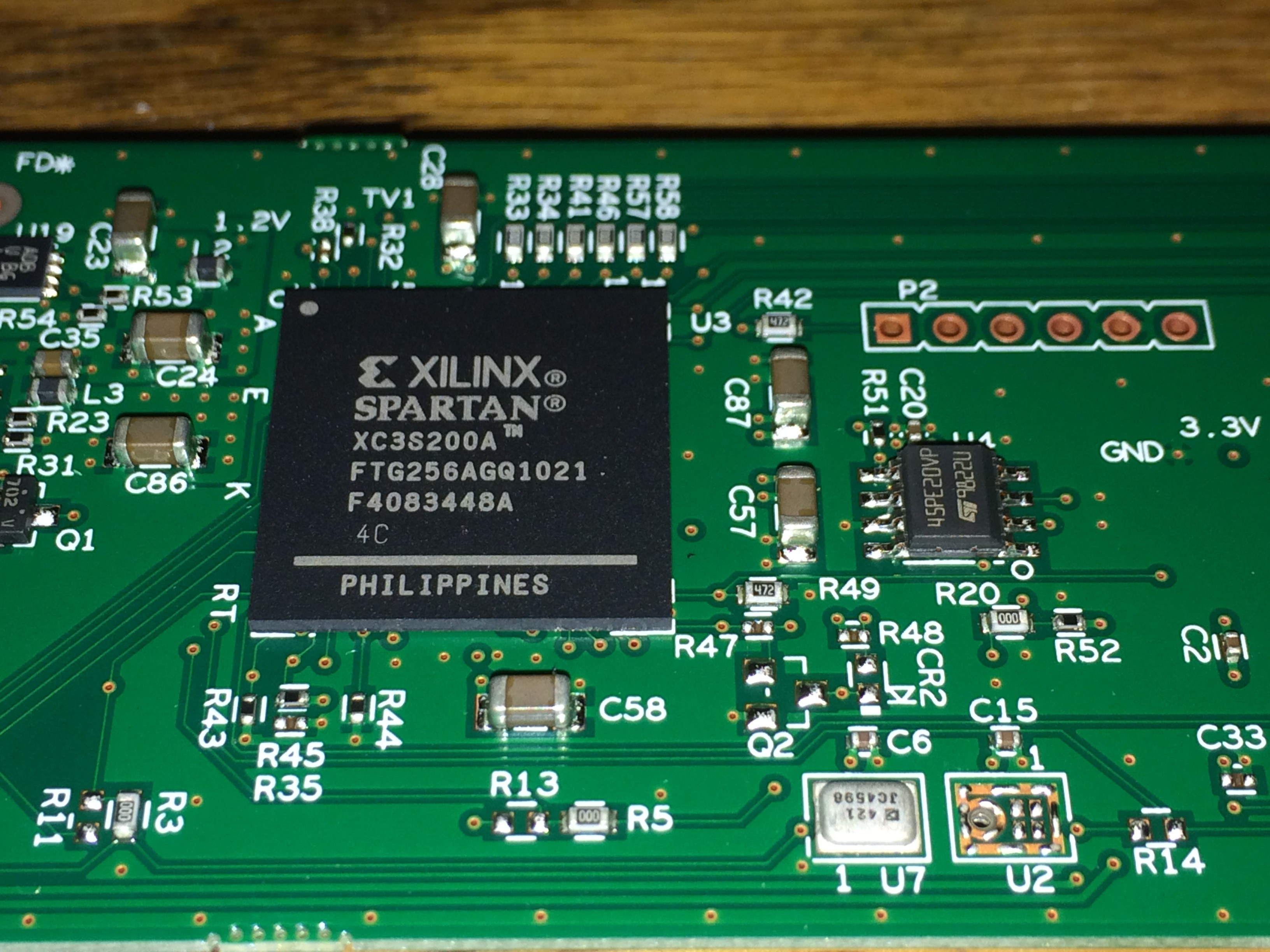
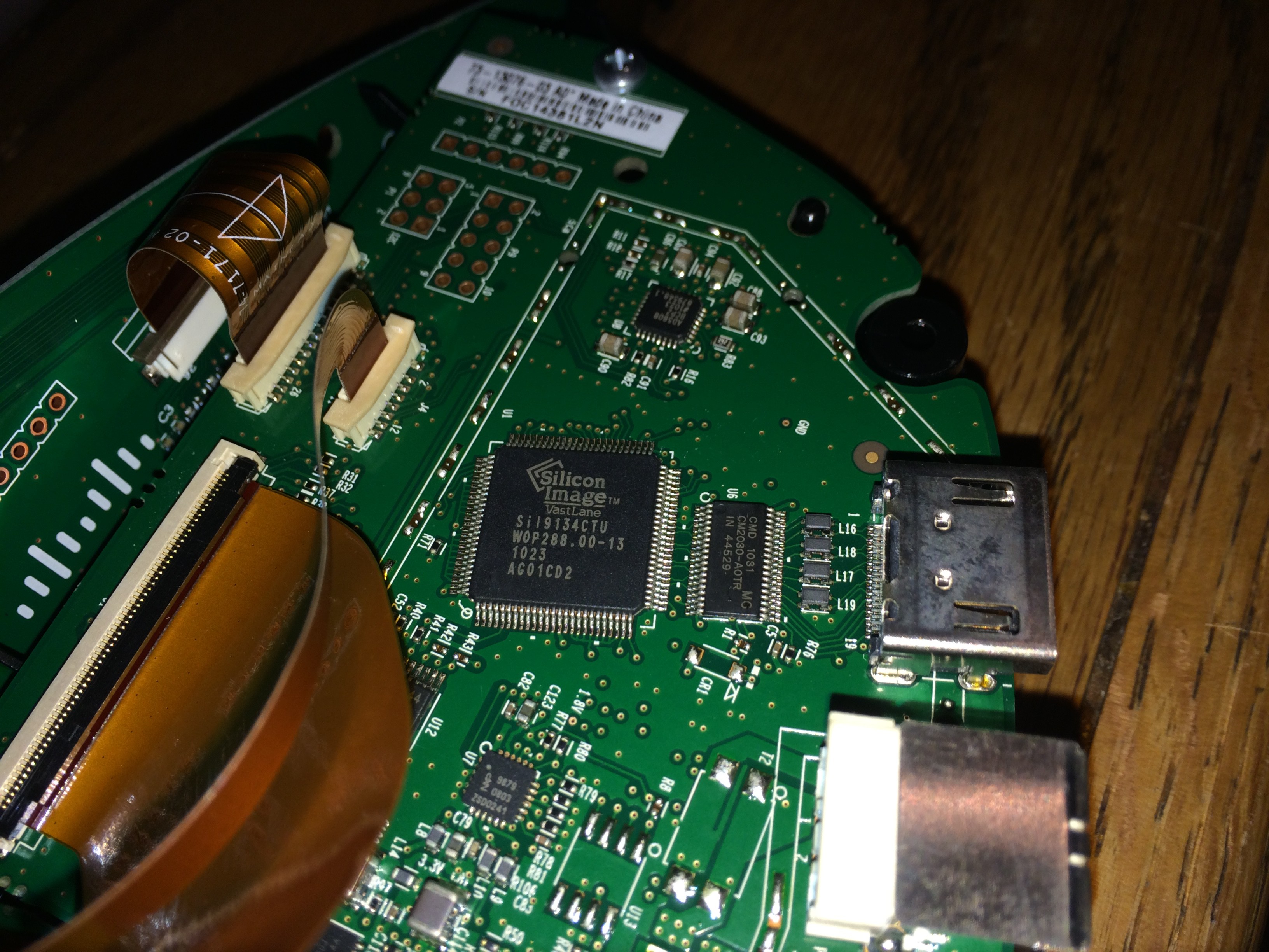
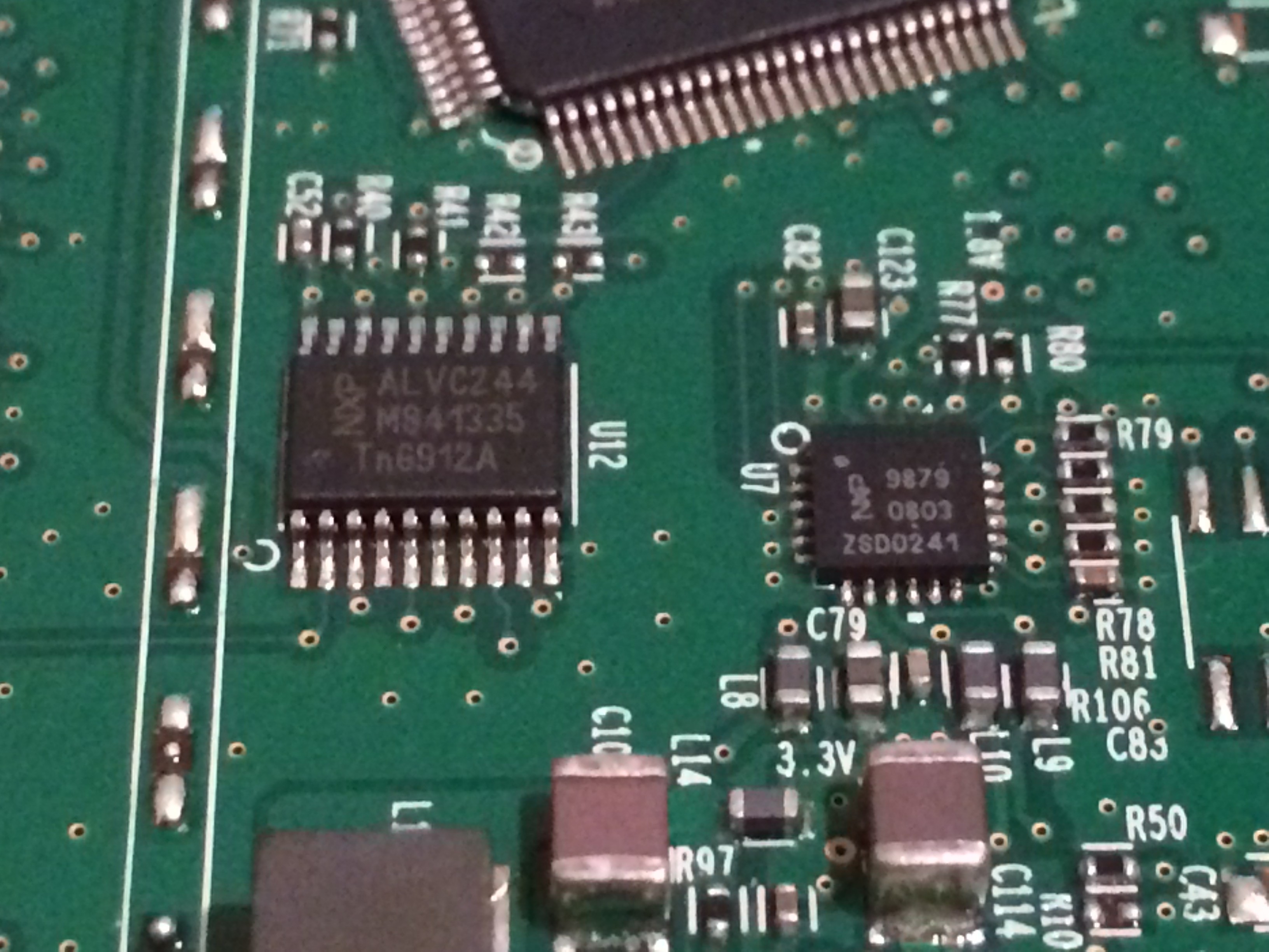
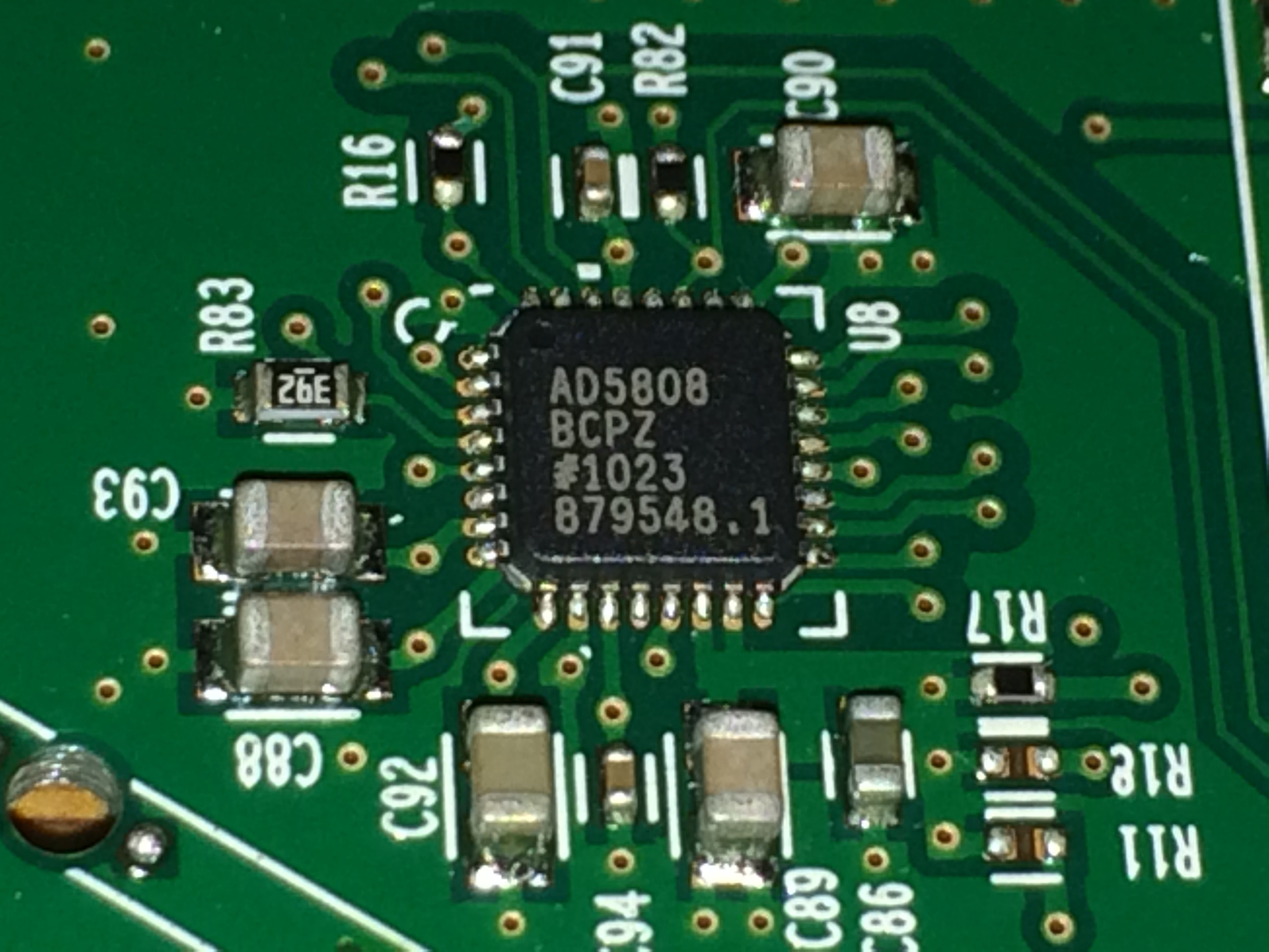
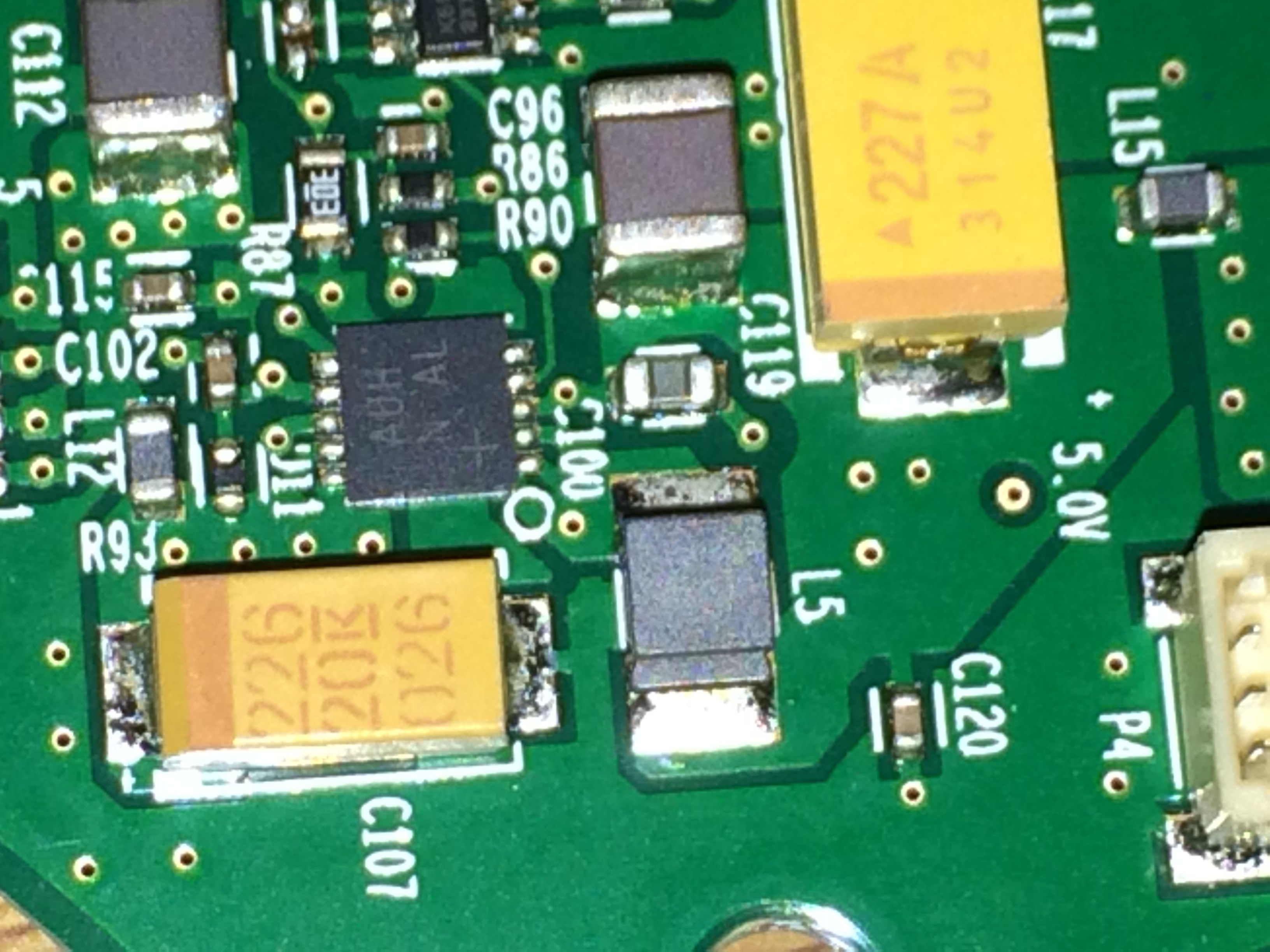
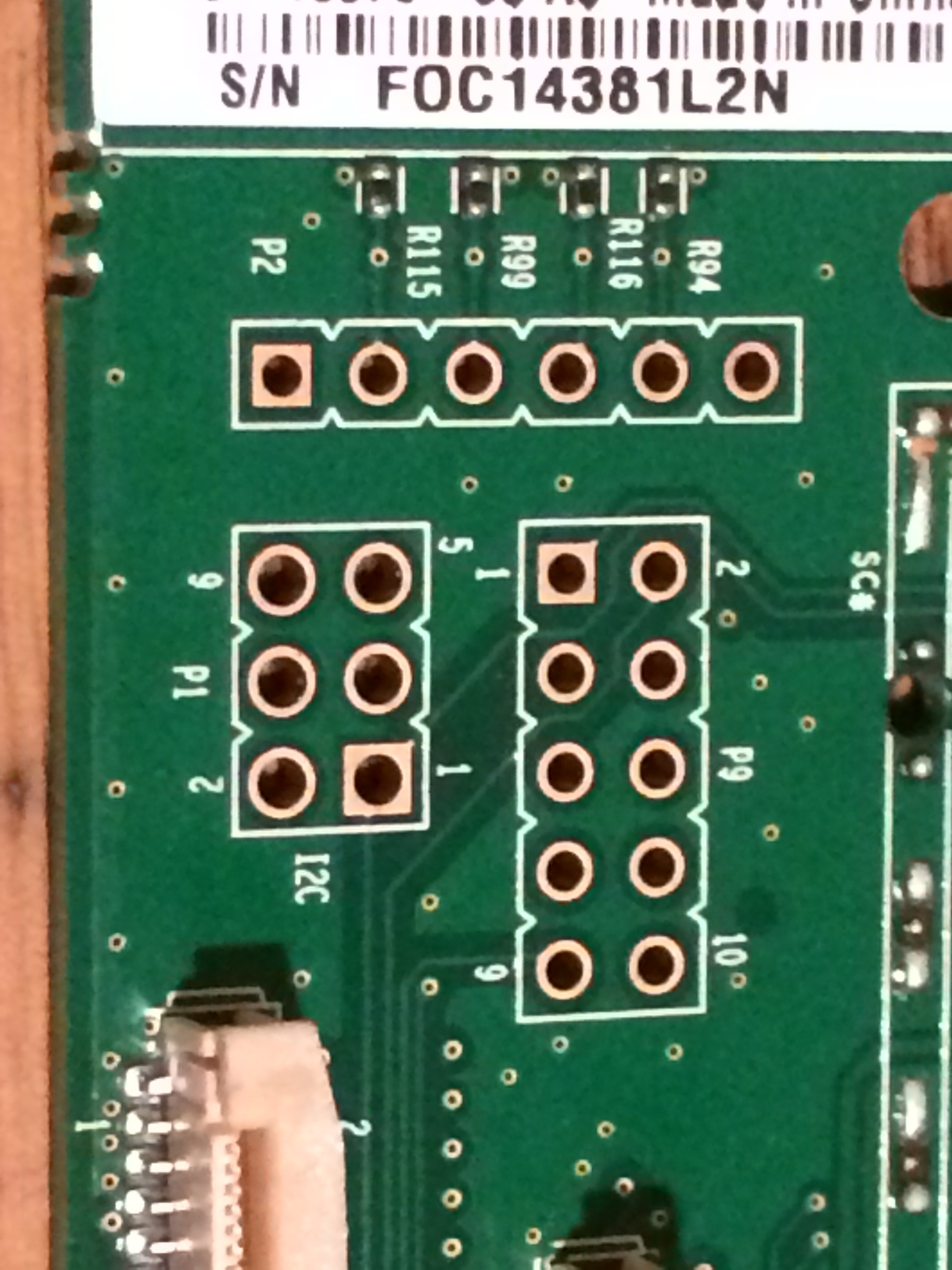
I also tried cracking open the set top box to try and look for a UART, look at what ICs are being used, and look for JTAG. I didn't think to take pictures. Inside the plastic shell is a metal box that looks like it may be glued to the shell in some way. I can't see how its fastened to the case but there are other pieces held on by glue and I heard that tape peeling sound when I flexed the shell trying to see if there were clips holding the box in.
I've decided to turn back and try to do some non-destructive probing first.
I expect Cisco has the client-server communication locked down and encrypted but maybe there is something open I can go after, either for a known vulnerability, or try fuzzing and see if I can find a weakness.
The system has 2 USB ports on it, maybe I can get to a shell through one of those somehow. It might also be possible that some pins on one of the HDMI ports might connect to a UART and I'll get lucky.
I hope I can dig up some hardware info on this but it seems like there was never a fire sale on the units which many be why more of these didn't wind up in the hands of hackers. If anyone does have a source of info, please point me in the right direction.
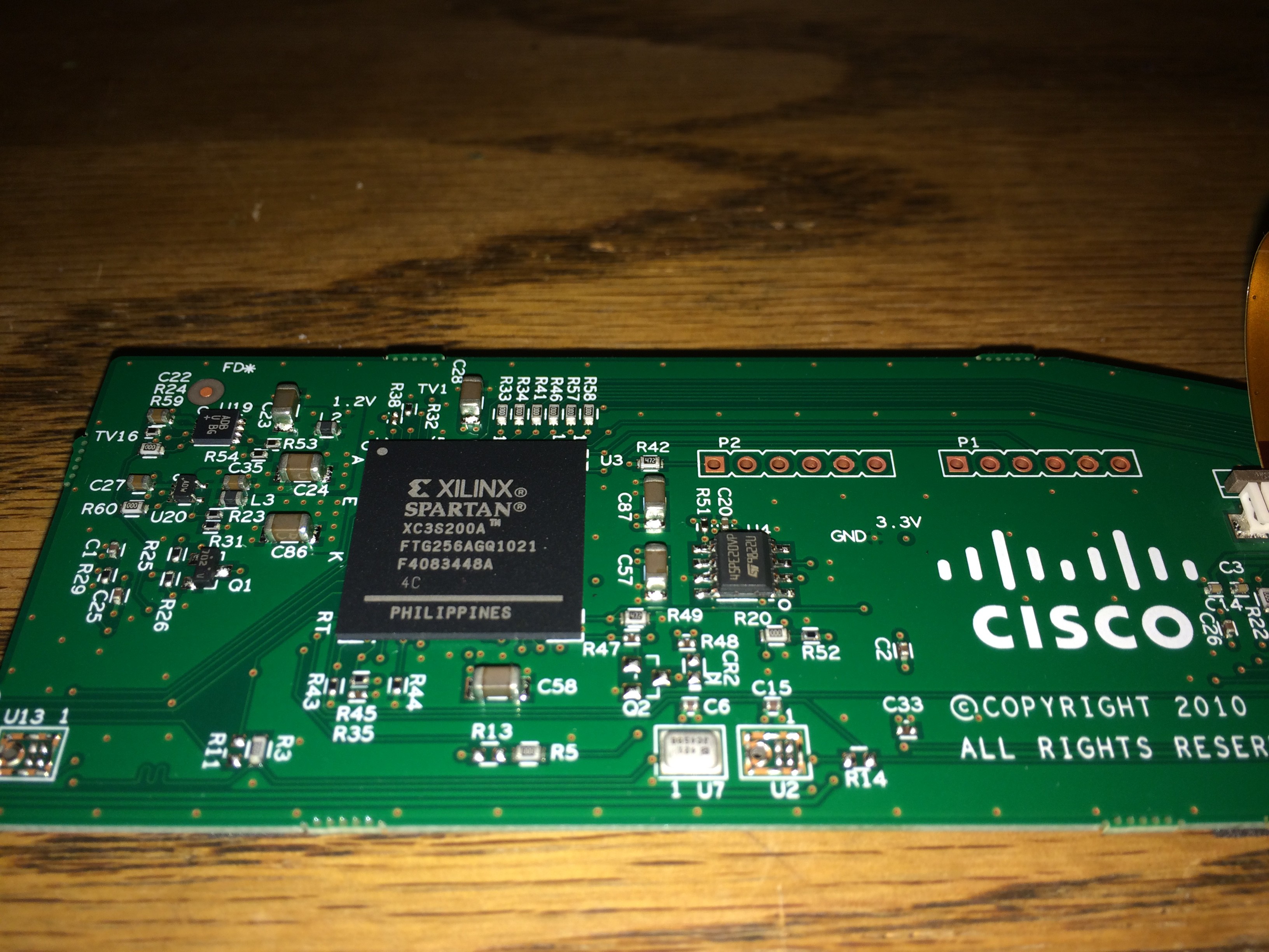
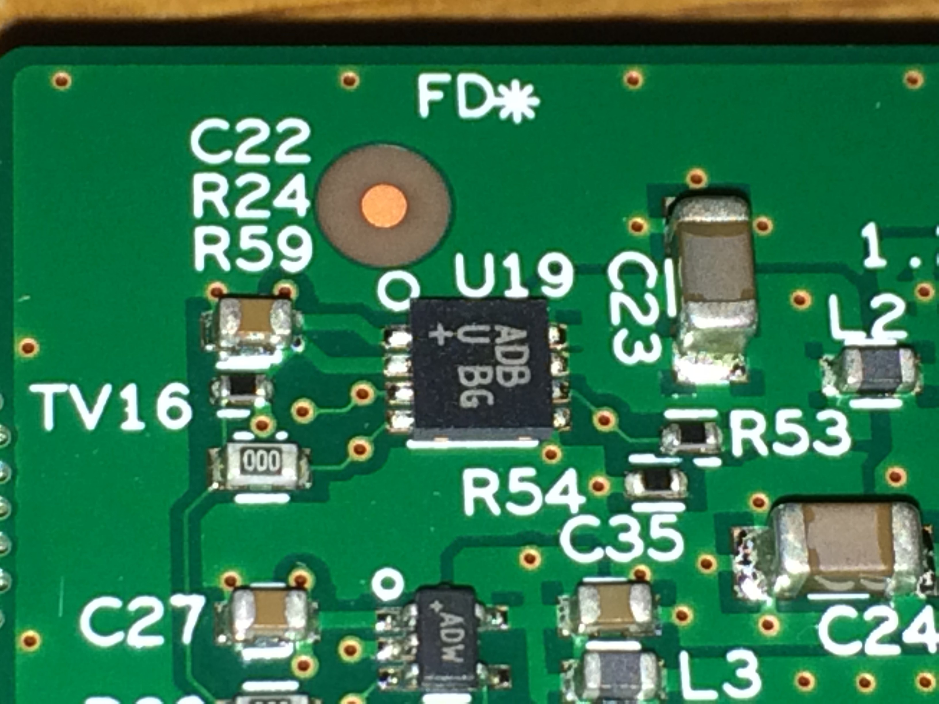
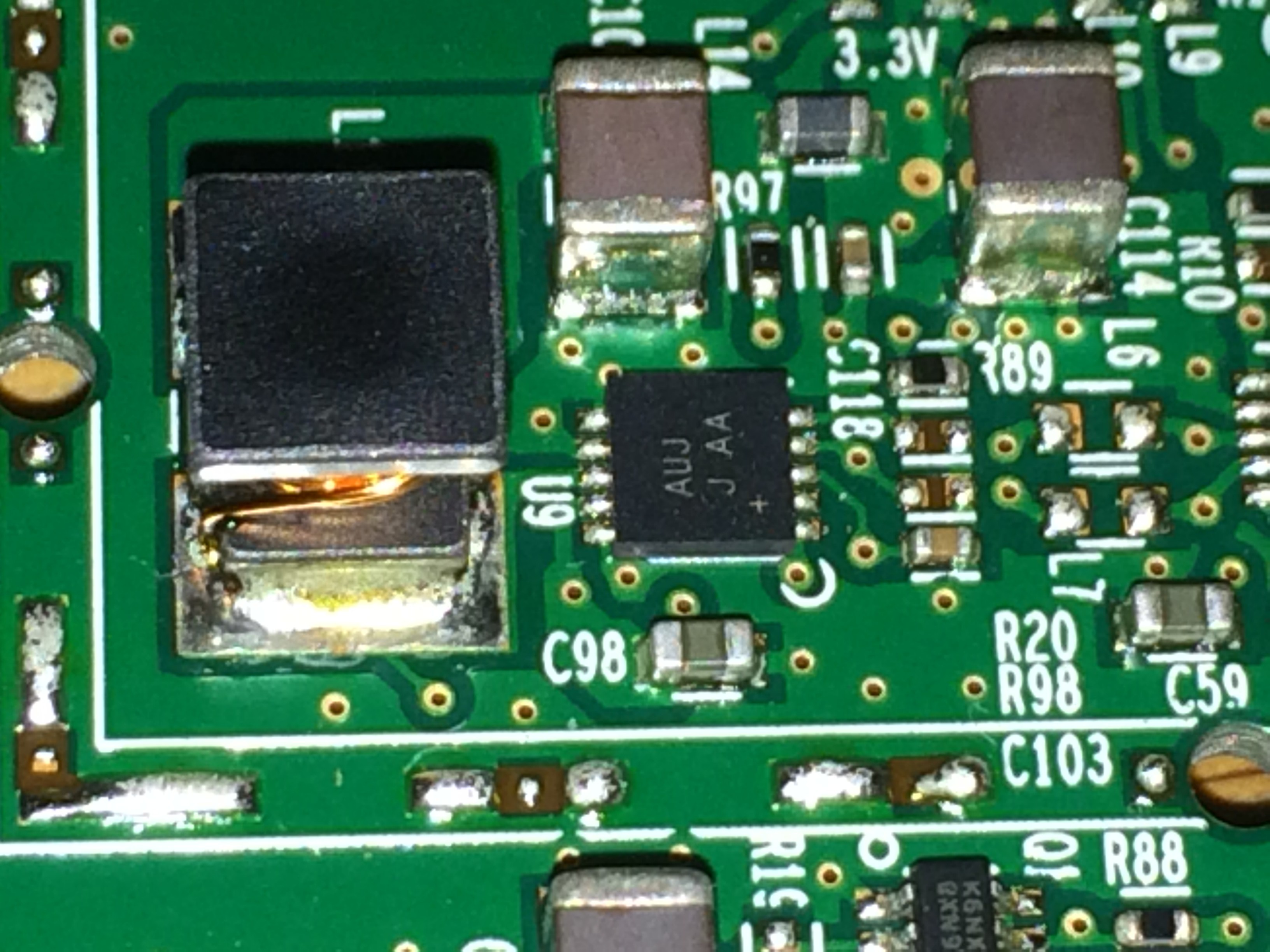
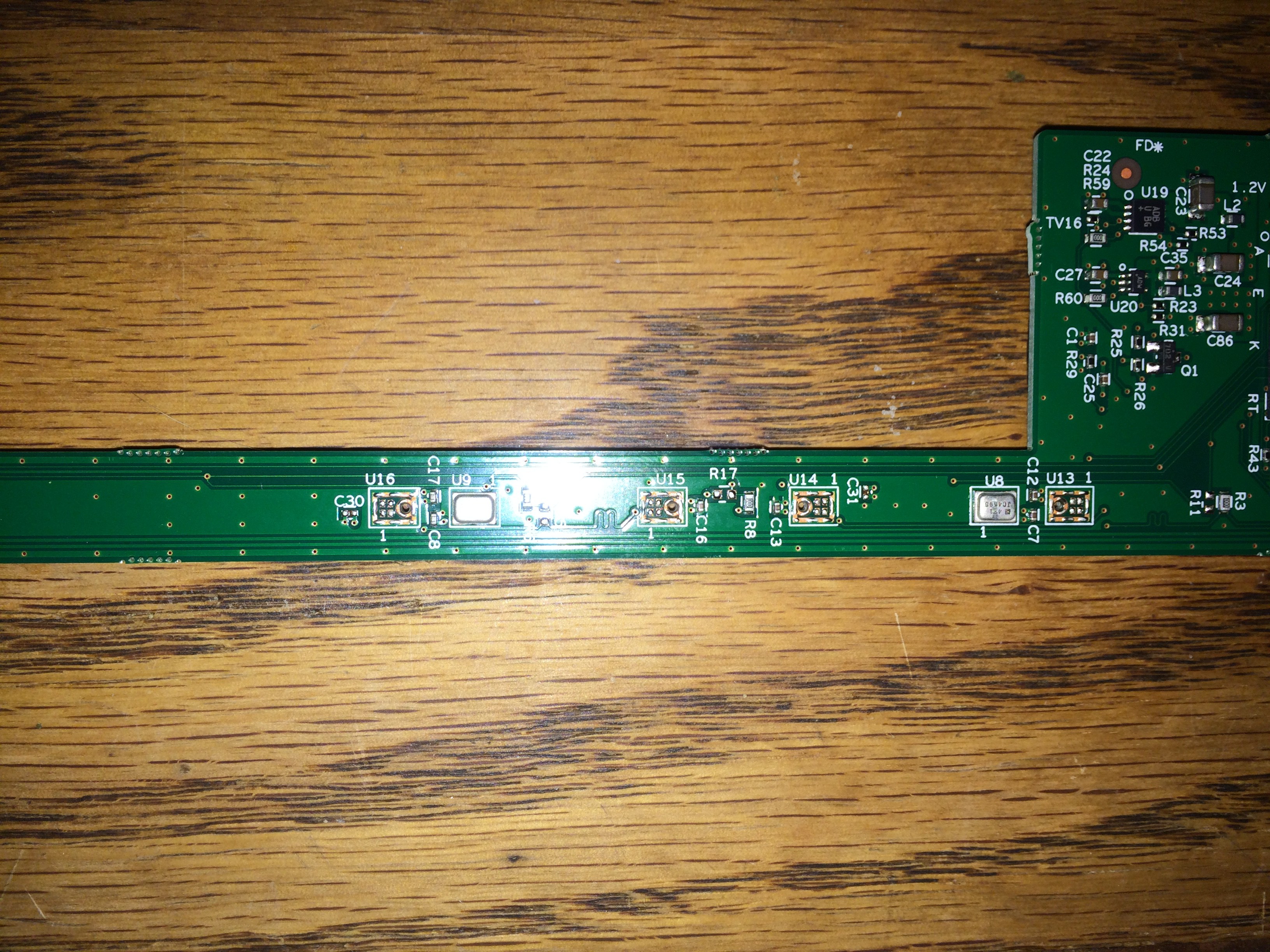 These features are really small and it was hard to grab an image. There is something that looks like a segmented border around a big via and 4 pads. They are labeled UXX but I can't spot any ICs on either side. The front fascia has mesh covered slot where these features are. My guess is they are used to pick up audio using capacitance, but that's a wild guess.
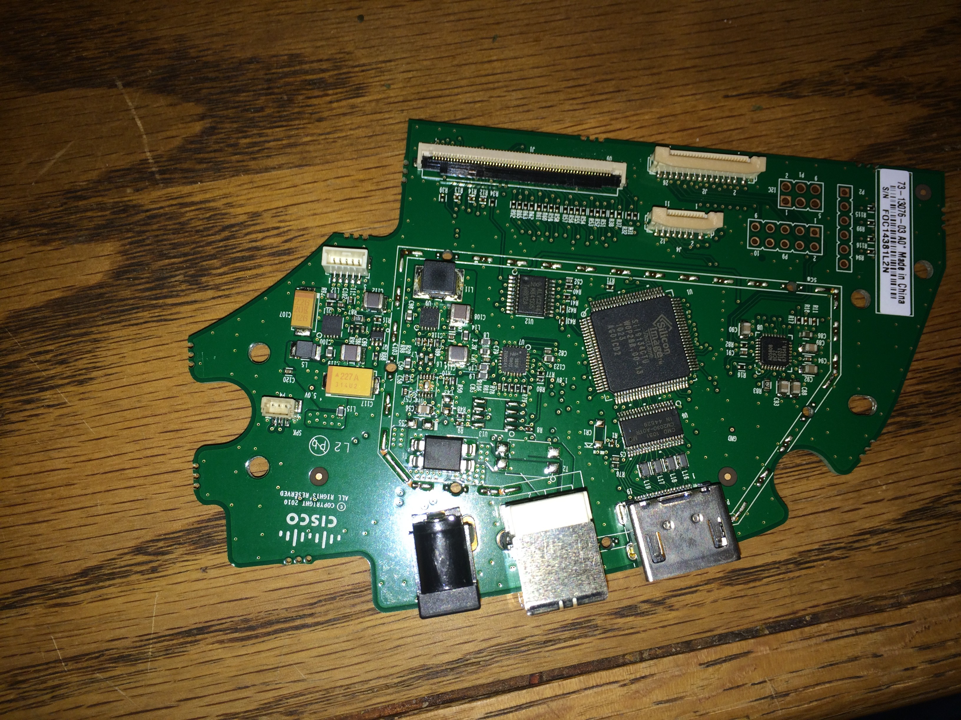
 The_Mekon
 frankstripod
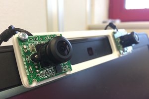
 Domen
Domen
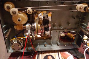
I was wondering if you got any further on the Umi? I acquired one and trying to create an inexpensive video presence in an audio studio to see into recording rooms from the control room and visa versa. I dug into it and got the shutter open, disconnected the motor so it stays open and got signal to an hdmi matrix router to switch between sources/outputs. I haven't been able to control the gimbal or zoom though. Total newb on circuitry and I have it working, just would love to be able to control the Zoom/Pan/Tilt functions bypassing the unit. Also wondering the voltage of the power input on the back of the camera. Might be able to get an adapter to fully power it through AC but can't find ANY info on it. Any help would be much appreciated. Cheers!