 Stefan Lochbrunner
The project that led to this was the first version of the ATtiny prog board which was inspired by the Digispark. It was around the time of the Kickstarter where I saw it being plugged into a breadboard and its power rails. Since that's a quite smart idea I built the prog board to do the same in order to decrease its width. However, this has the downside that the board can only be used on one side of the breadboard (which is only a slight inconvenience but if it can be avoided it helps to reduce the mess of wires on my bench/desk).
Until recently I haven't seen this being done anywhere else. Most of these boards are in a DIL configuration that requires more space on a breadboard (granted, two pins don't weigh in that much on larger packages but I think they do in this case).
Anyway, to circumvent the problem and make the prog board usable on both sides of a breadboard I threw around some ideas:
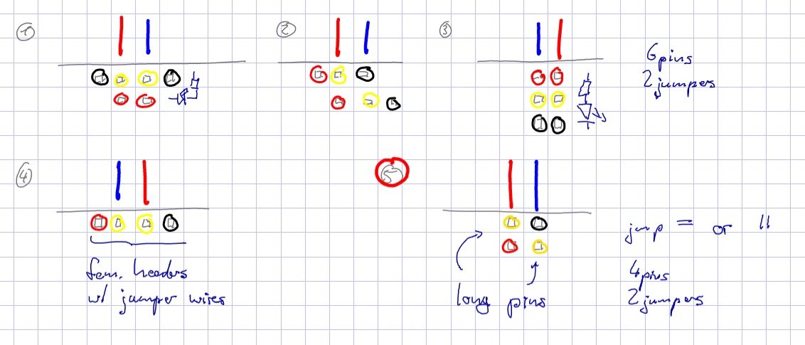
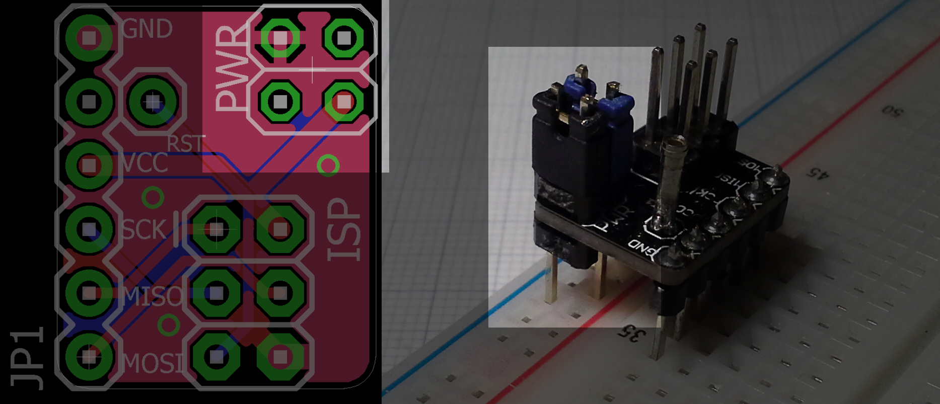
If you now place this assembly on the other side of a breadboad, where the rails are inverted, all you have to do is connect the jumpers horizontally. To illustrate this better here's the board layout and picture of an ISP breakout that uses this system:
As you might have seen, I use this on most of these widgets. It solves a problem but also creates a new one if you forget to place the jumpers correctly. Therefore I've been thinking about some sort of rectification attachment to replace the jumpers, though I'm worried that an off-the-shelf rectifier would have a too high voltage drop. But then again, if I was using such a rectifier, I might as well put it on the board and omit the PWR thingy.
Edit: I added a '+' to the silk screen to indicate the Vcc pin which should make setting the jumpers easier. (I didn't bother updating all the images for such a minor change but I'll put some here)
Discussions
Become a Hackaday.io Member
Create an account to leave a comment. Already have an account? Log In.