i have finished this project. I just need to post the final log. I did manage to take care of the overheating problem.
0%
0%
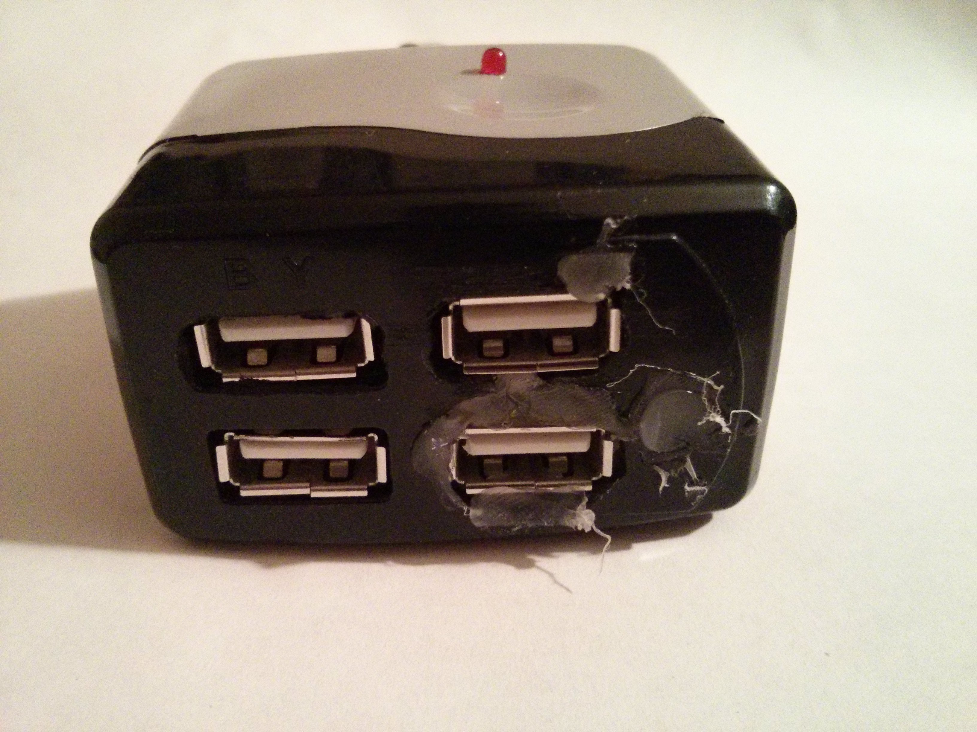
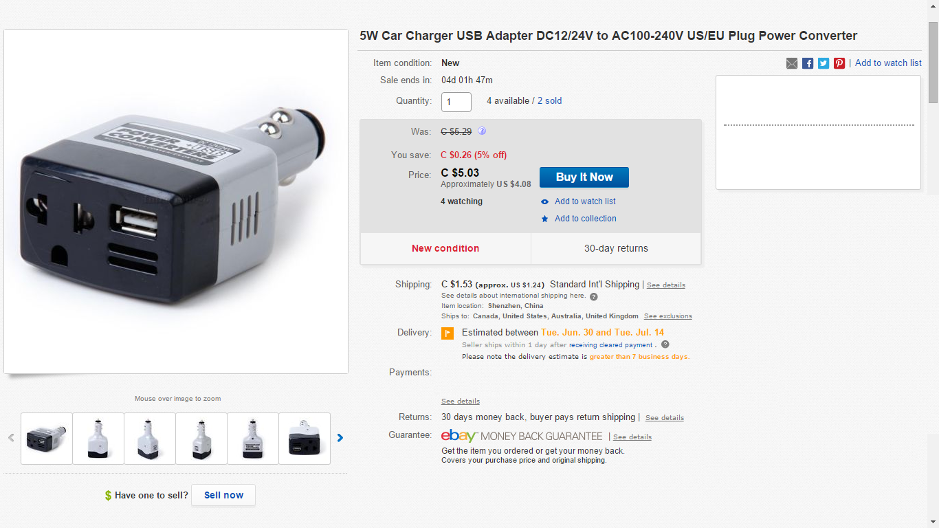
Car USB charger
A car usb charger based on the MC34063 chip
Become a Hackaday.io member
Already have an account? Log in.
Just one more thing
To make the experience fit your profile, pick a username and tell us what interests you.
Pick an awesome username
hackaday.io/
Your profile's URL: hackaday.io/username. Max 25 alphanumeric characters.
Pick a few interests
Projects that share your interests
People that share your interests
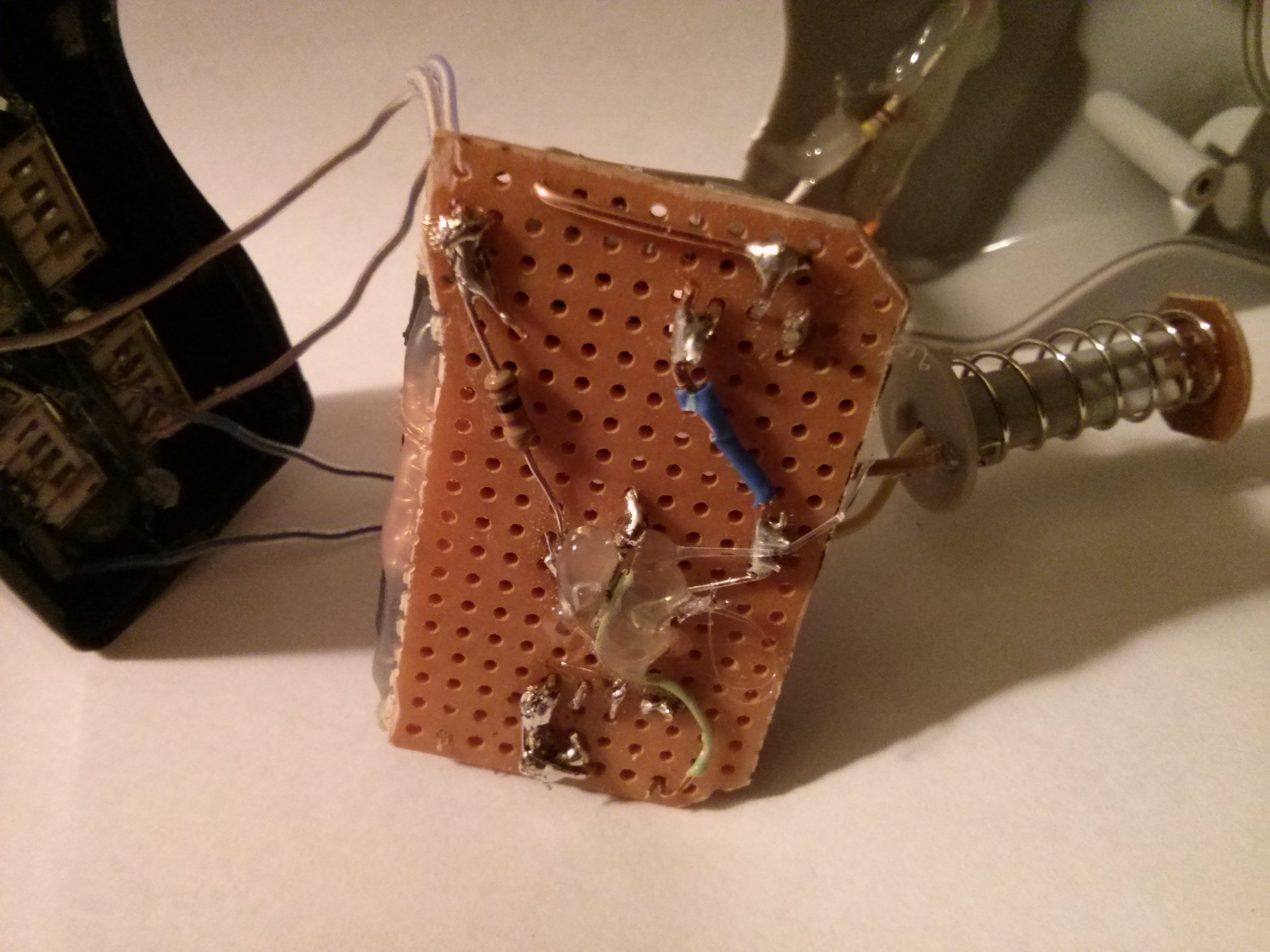
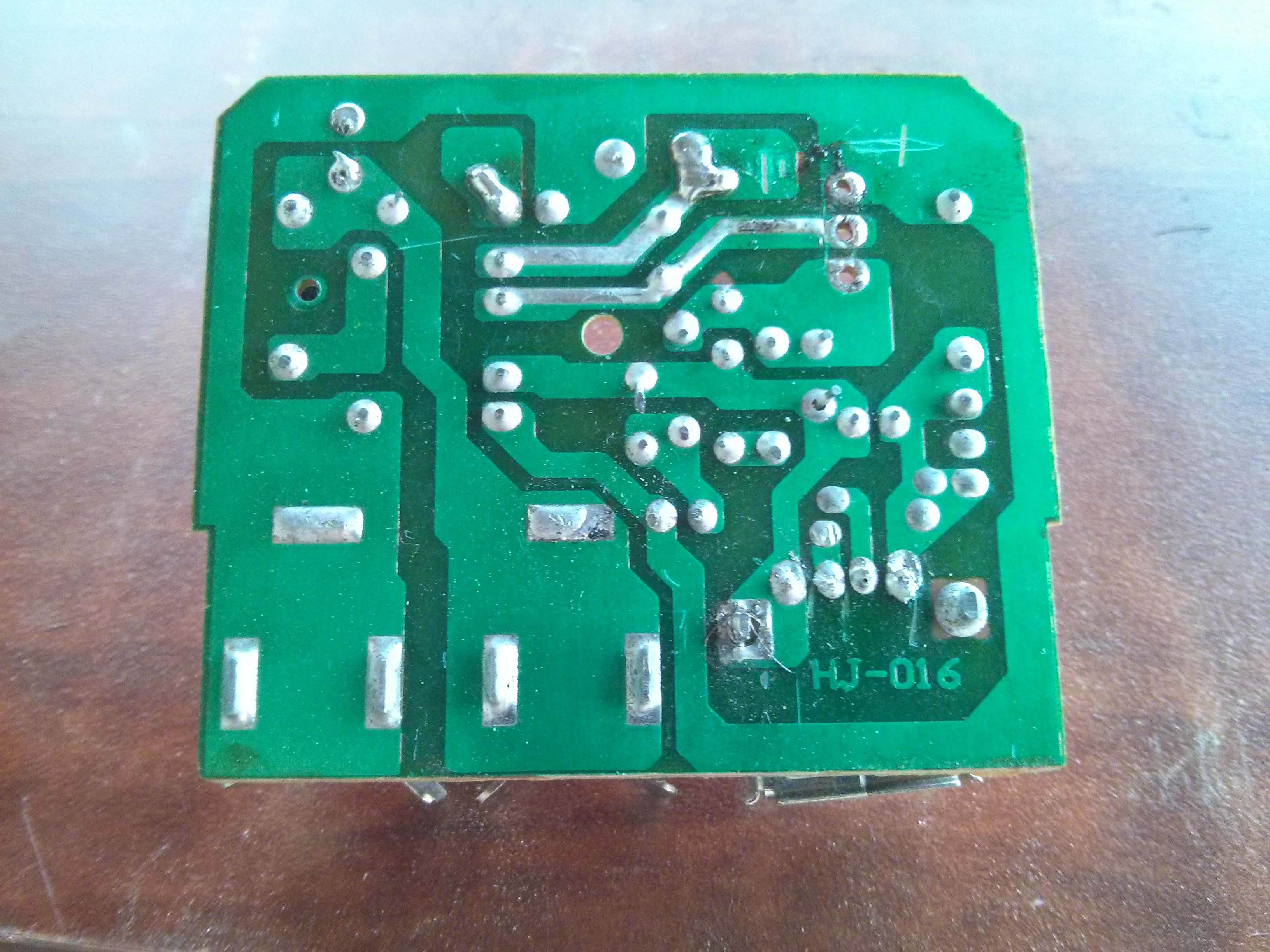
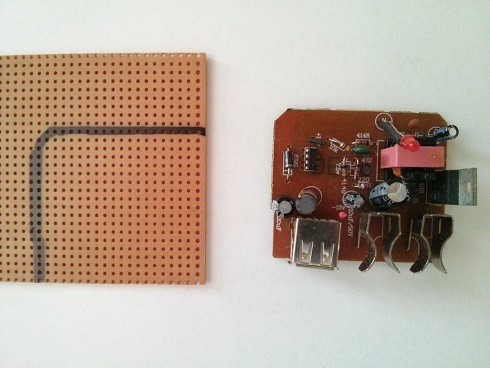 Outlining the board.
 zakqwy
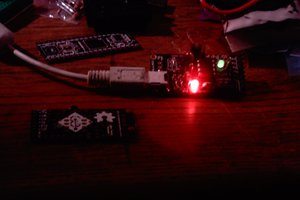
 Ethan Durrant
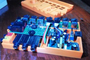
 Patrick
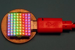
 Alex
Alex
Can we also replace the car keys as we have for the car USB chargers? I think https://replacecarkeys.com/ is offering so!