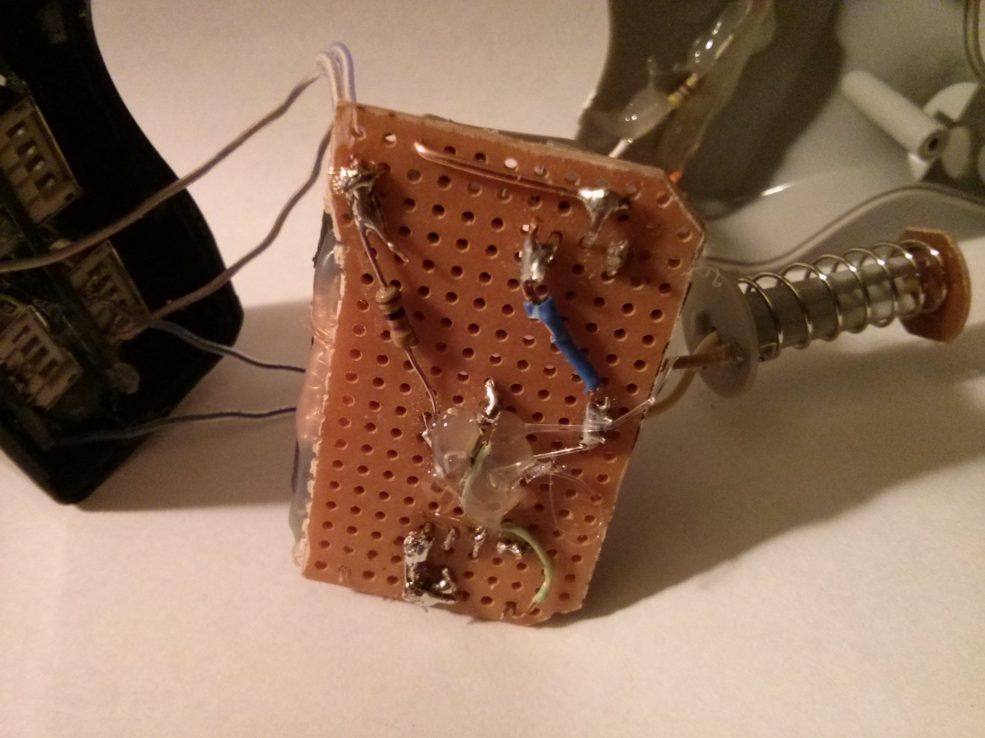
The bottom all soldered up after getting rid of the heatsink. That green wire near the bottom provides the regulator's power and the blob of hot glue holds it in place. I also replaced the wires from the spring and PCB since i did not believe they would handle the current.
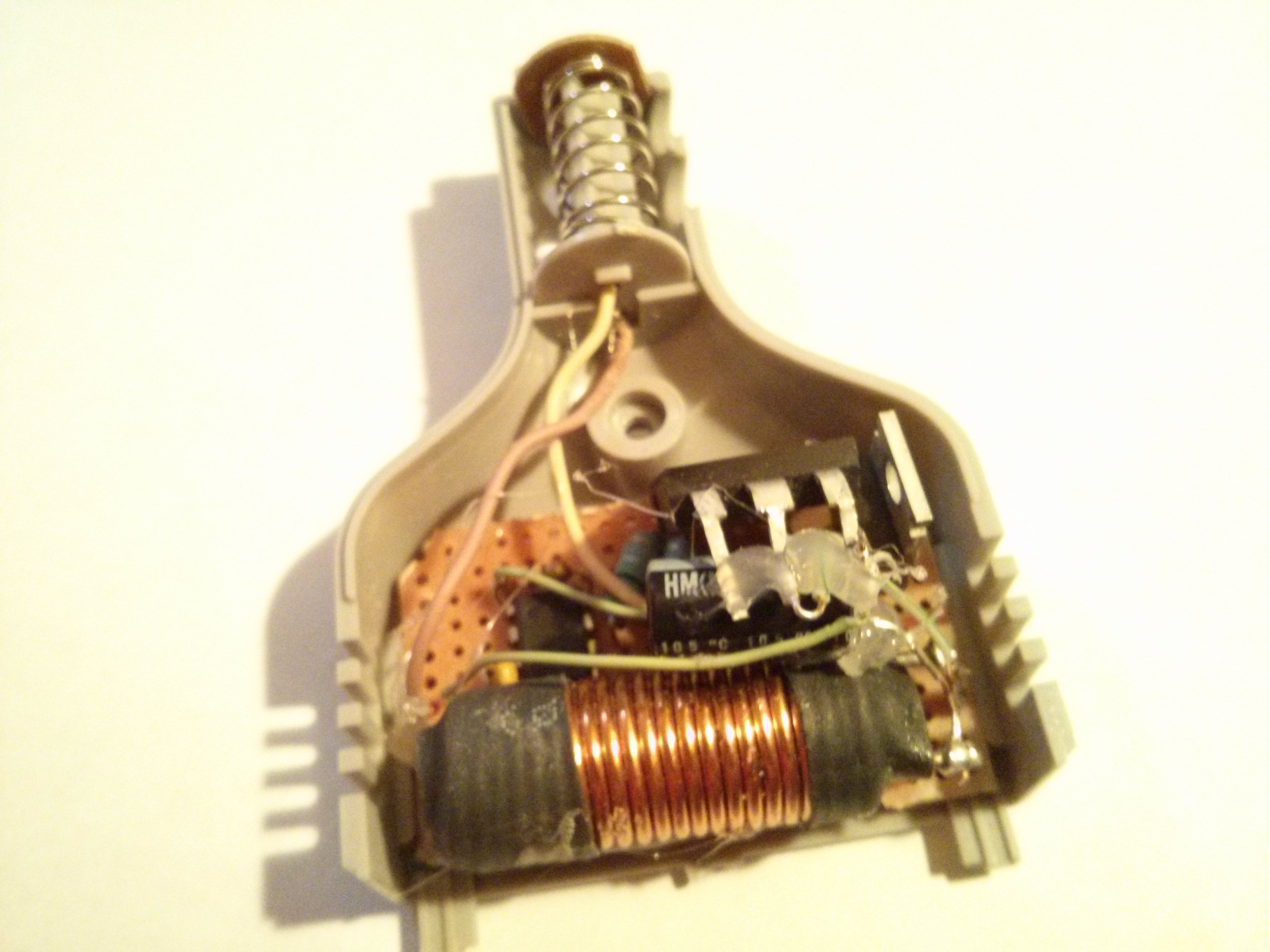
A test fit of the board. I ended up having to remove some plastic off the casing to get it to fit well.
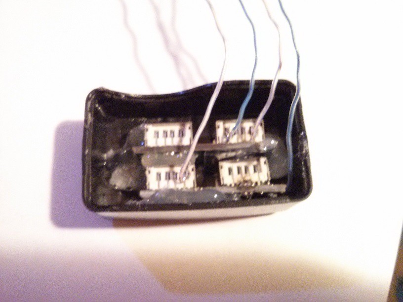
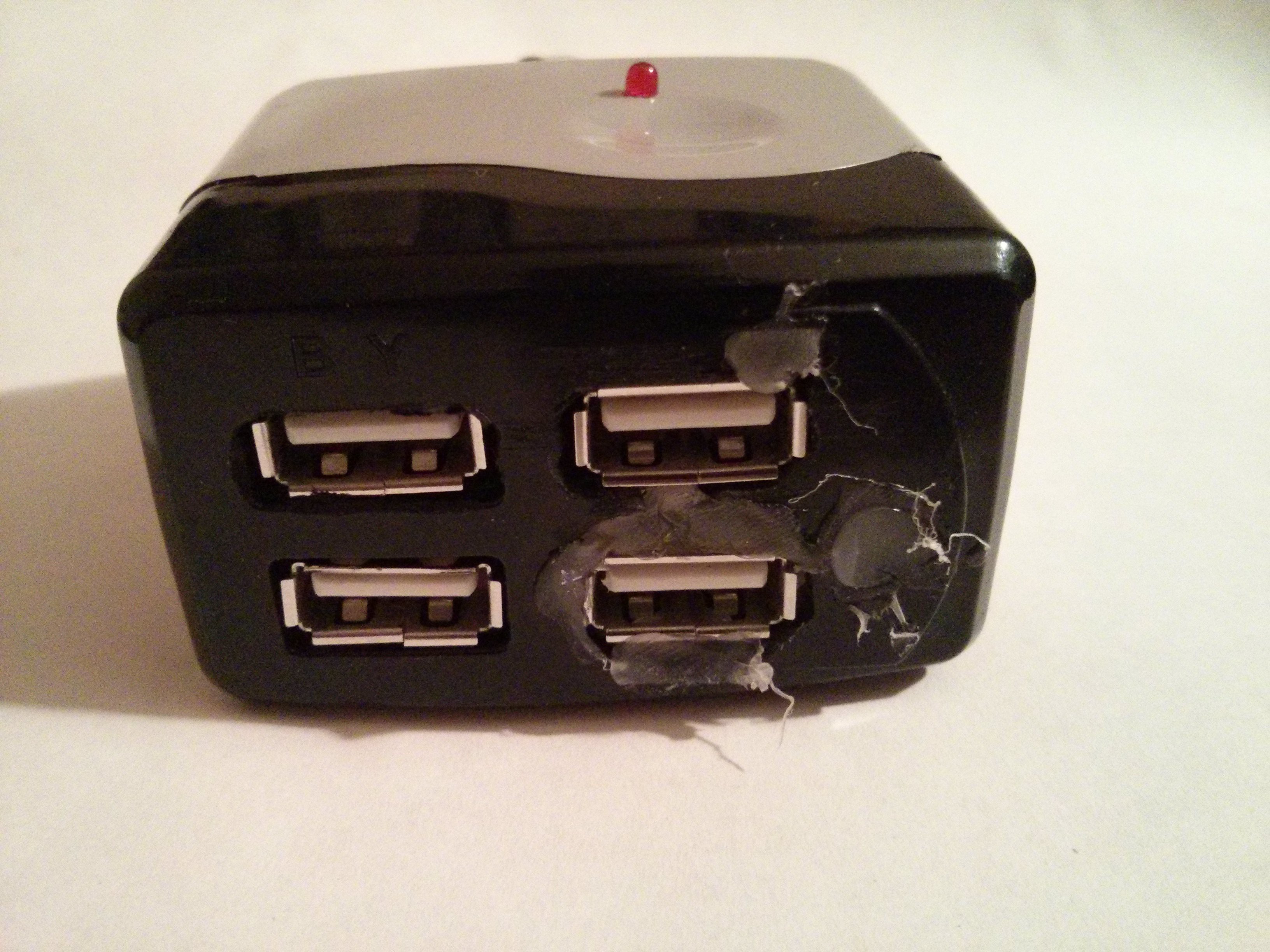
The usb ports. When the hub was still intact, I tried to desolder and remove the USB ports. I couldn't get them off. Then I realized that if I kept the board and cut off the excess, i could the left over board as support. So I cut the row of 4 off the main board and cut it into two pieces. A test fit showed it was still a little too large, so the extra on each side of the ports were cut off. I then soldered on the wires for power. I also shorted out the data pins to force AC charging on my cellphone. Later, I cut out the holes in the casing and hot glued the ports into place.
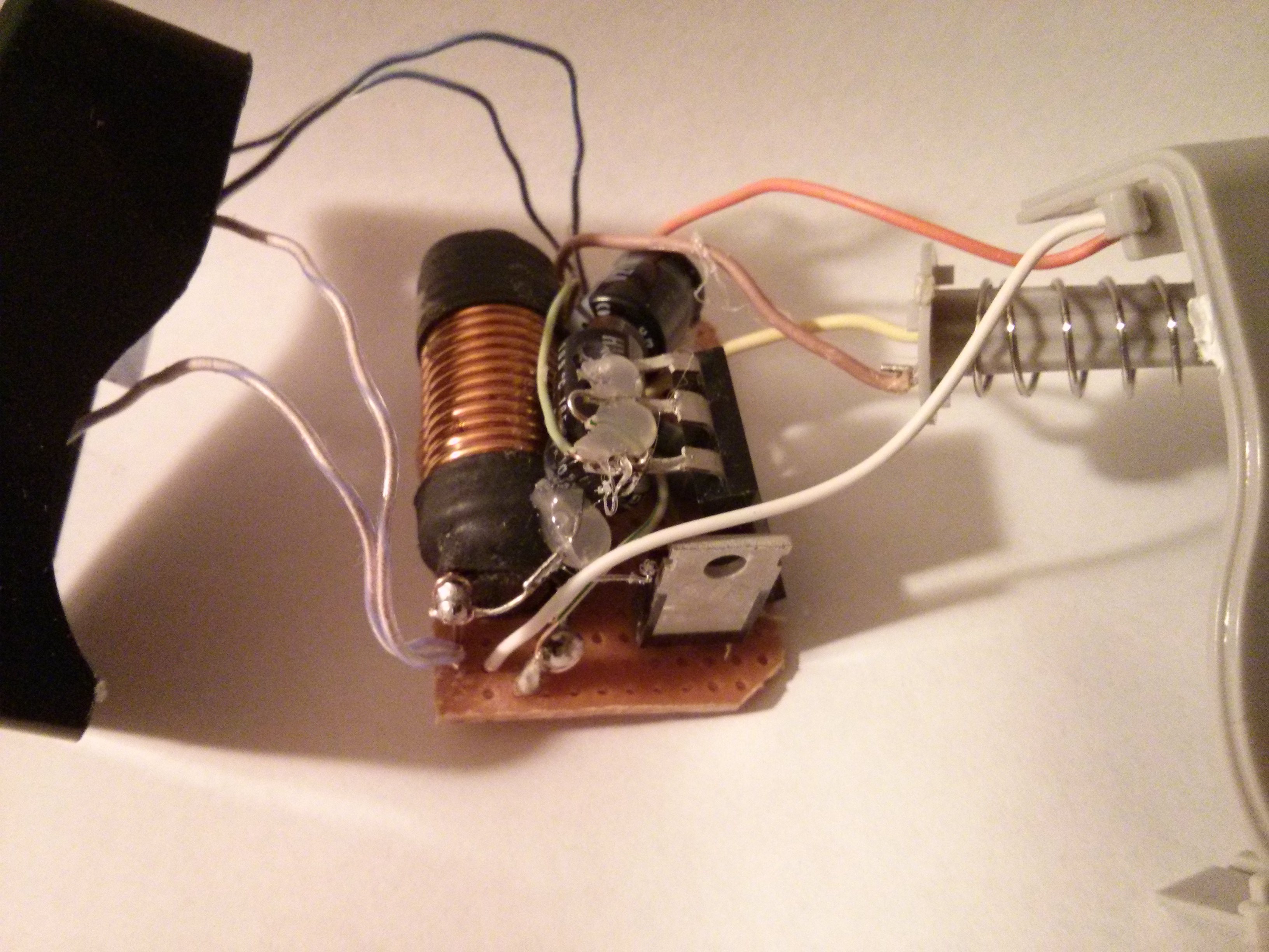
The top view of the circuit after connecting all the wires. I also ended up having to cut off a bit of excess board next to the inductor since it interfered with the usb when I tried to close the unit up. Orange/white is the red led. The two blue, clear white wires are for the USB. Yellow/Brown is for the 12v from the car.
The finished unit. A test fit in a car showed that it was too tight, so I ended up removing two metal bearings (not shown). A quick test showed that it regulated to 5.3 volts so i left at that. However, on its maiden voyage, i noticed that the area near the fet was warm, which i expected. What I didn't expect was another area was warm too. A quick dis-assembly and foolishly putting my finger on the diode resulted in a burnt finger. The fet was hot as well, but not enough to cause great worry.
That evening, I used an N-FET as a dump load to test how long it could run and the result worried me. After about 45 minutes, the voltage regulation started to fail, letting the voltage spike up to 7 volts for moments at a time. I stopped the test and left the system to cool down. I pulled it apart again and checked what was hot. The diode and the Fet were a given, but so was the inductor. When I tried to pull out the board, I found that it was stuck to the plastic. After a good tug, it came loose and found that the hot glue blob had gotten soft. I checked the other blobs and they were all soft. After it cooled down, I turned it on again and the system was regulating to 5.3 volts again.
So I was left with a choice, leave it at that, or put back the heat sinks.
I chose heat sinks.
Discussions
Become a Hackaday.io Member
Create an account to leave a comment. Already have an account? Log In.