 BlueMate.com
-
1Step 1
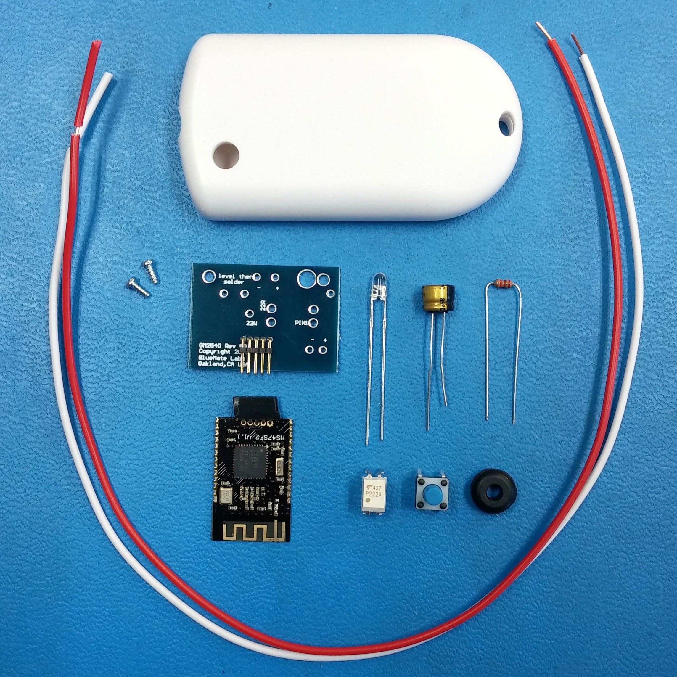
DIY Kit Parts
![]()
You can purchase an entire DIY Kit or Assembled Receiver from: bluemate.com
Identify and verify all of the kit components:
[From left to right, top to bottom]- (2) 22 gauge wires
- Plastic Case
- (2) Screws
- Printed Circuit Board (PCB)
- LED (Clear/Blue)
- Capacitor (100 microfarad)
- Resistor (2.2k Ohm)
- GM2540 Bluetooth Module
- Photocoupler/Photorelay (Opto)
- Tactile Switch
- Grommet
- Power Adapter (Not Pictured)
Tools required:
- Soldering Iron
- Solder
- Wire Cutters
- Small Phillips Screw Driver
-
2Step 2
Add Switch
![]()
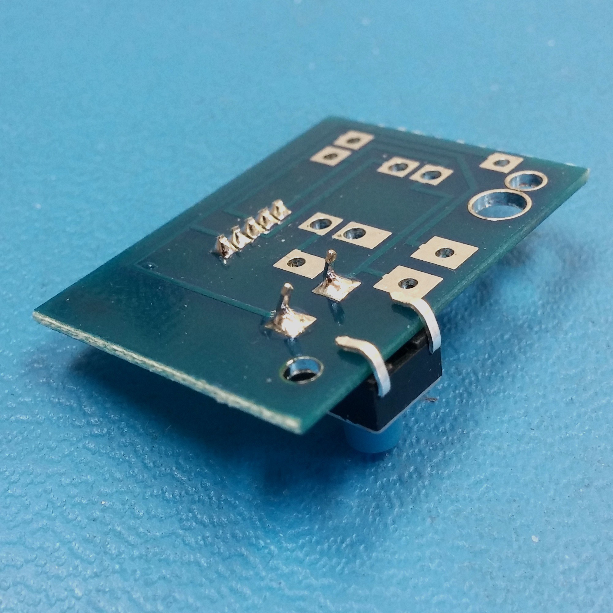
Place the tactile switch on the PCB as shown.
![]()
Bend the two overhanging switch leads around the end of the board, and solder the other two leads to the PCB.
-
3Step 3
Add "Opto"
![]()
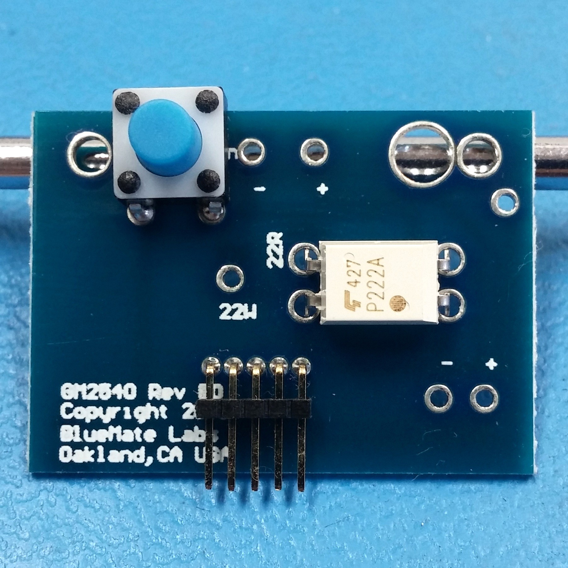
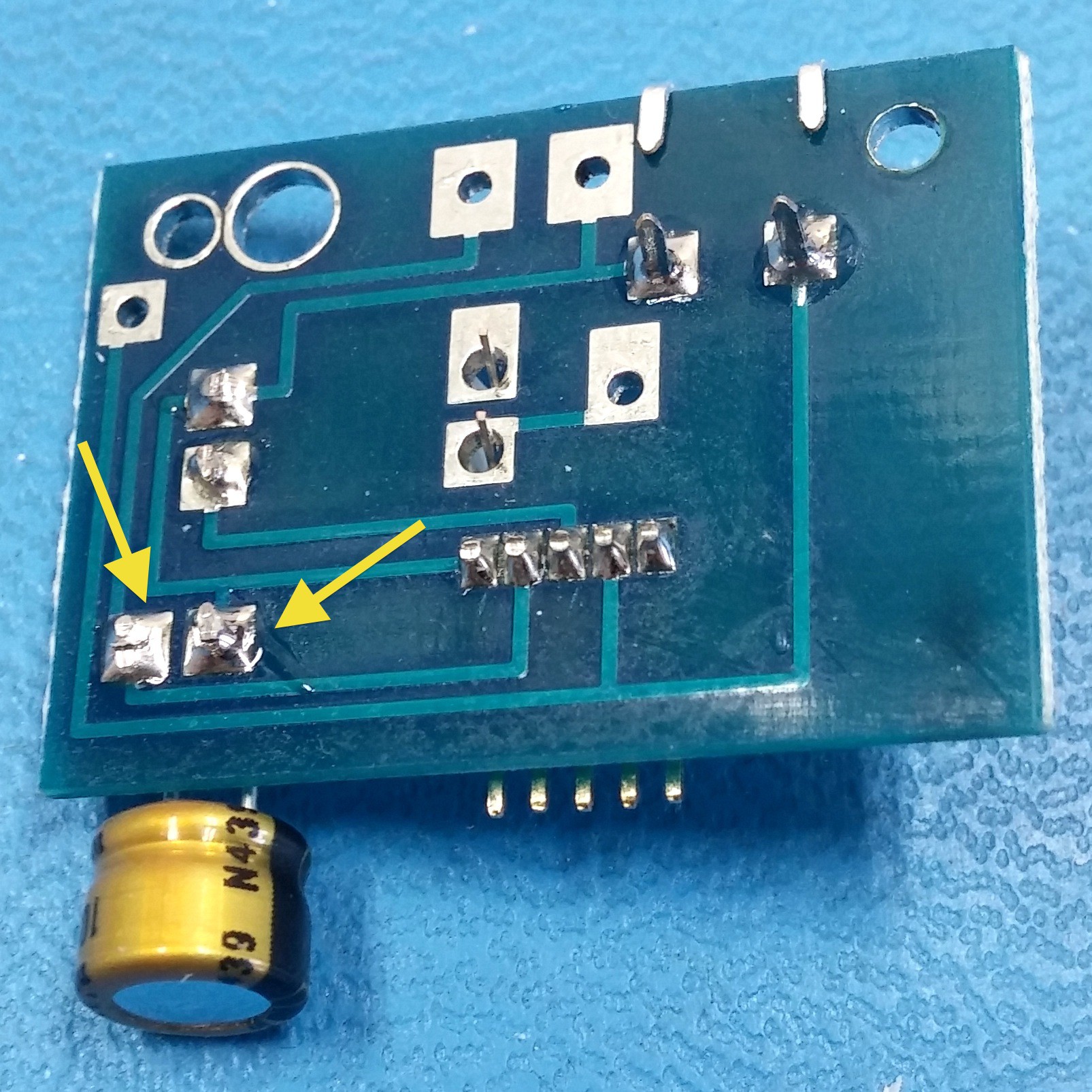
Place the "opto" into the PCB, note "Pin 1" with the dot shown on the lower right.
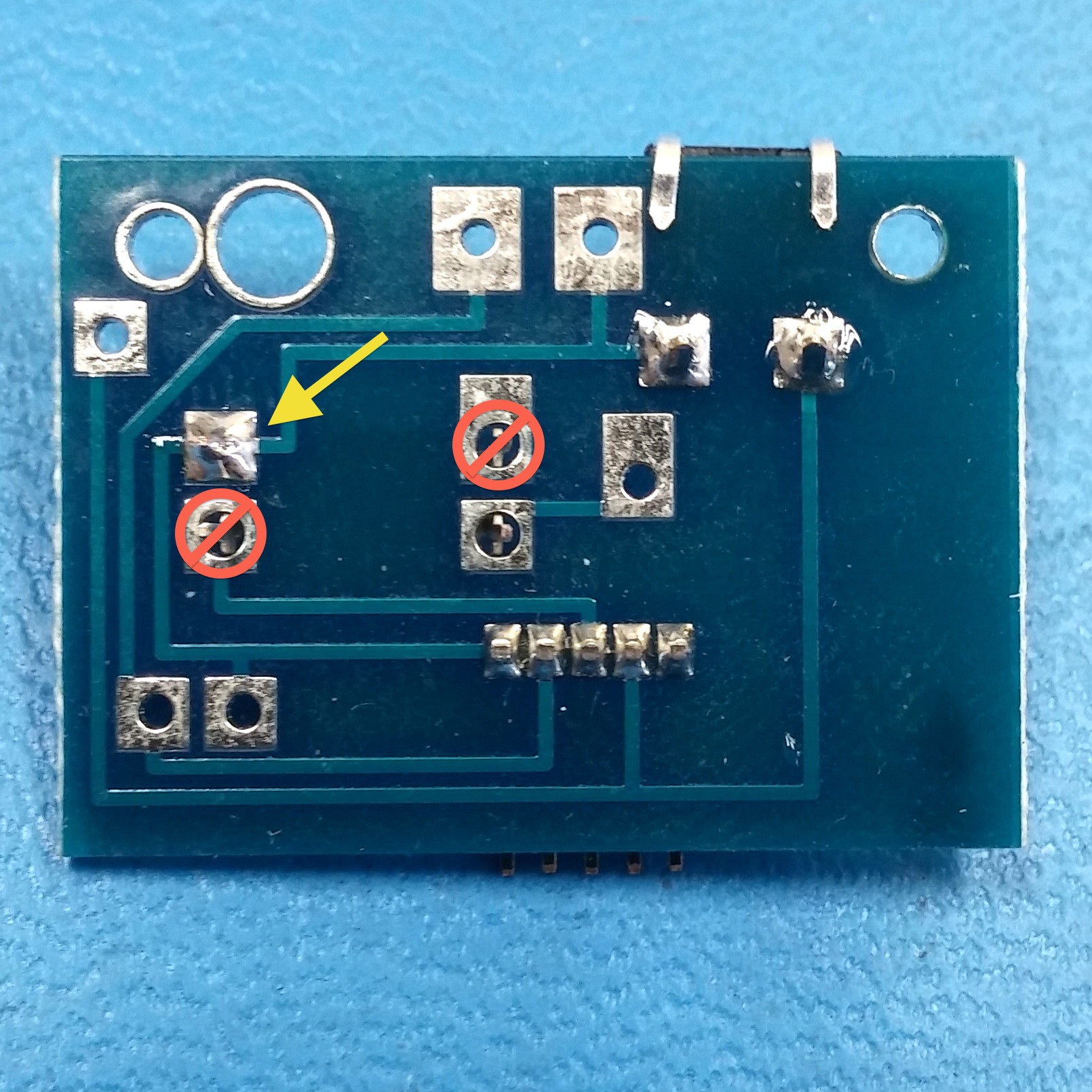
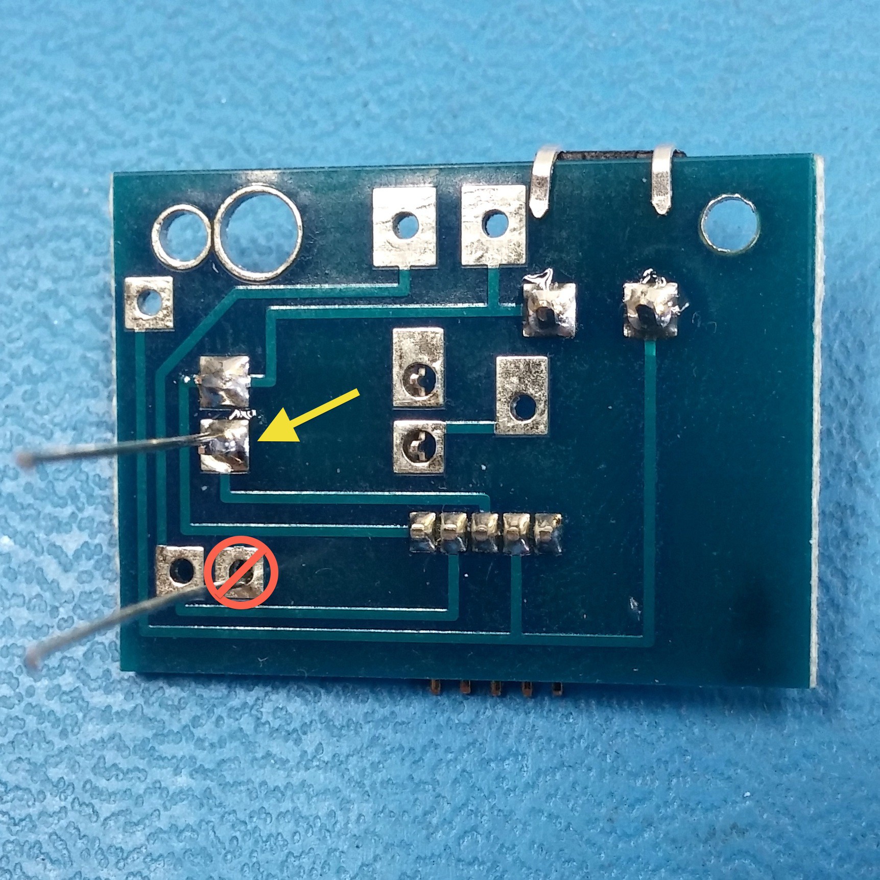
![]() Solder just the pin indicated with the yellow arrow, the other pins will be soldered with additional components later. Do not solder all of the pins yet.
Solder just the pin indicated with the yellow arrow, the other pins will be soldered with additional components later. Do not solder all of the pins yet. -
4Step 4
Add Resistor
![]()
Insert the resistor into the PCB, one leg goes thru the same hole as Pin 1 with the "opto" and the leg goes thru the hole marked "-" negative.
![]()
Solder just the one leg of the resistor along with the "opto" pin.
-
5Step 5
Add Capacitor
![]()
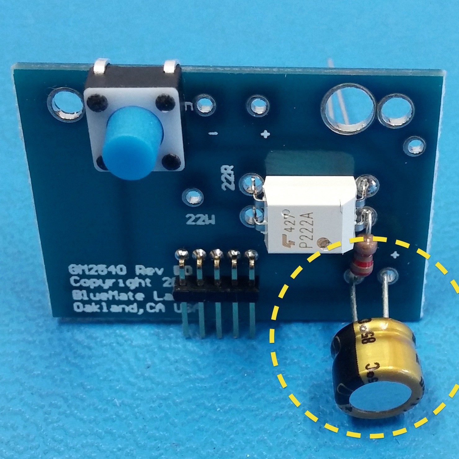
Insert the capacitor, note the polarity, the black band on the left indicates the negative side which goes in the same hole as the resistor. Leave the capacitor about a quarter inch out from the board.
![]()
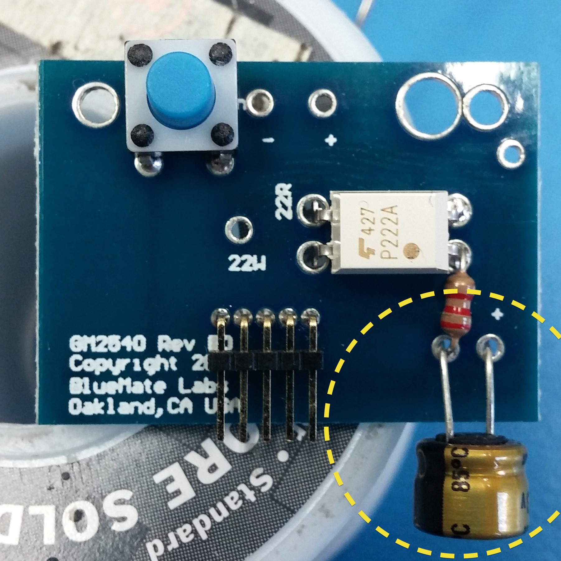
Bend the capacitor 90 degrees so that it hangs over the edge of the board.
Solder both leads of the capacitor along with the remaining leg of the resistor and trim with wire cutters.![]()
-
6Step 6
Add LED
![]()
Bend the negative lead (the slightly shorter one) like shown.
![]()
Push the LED and bent leg thru the bottom of the PCB until it is about flush with the board. Solder the bent leg, and trim the excess.
-
7Step 7
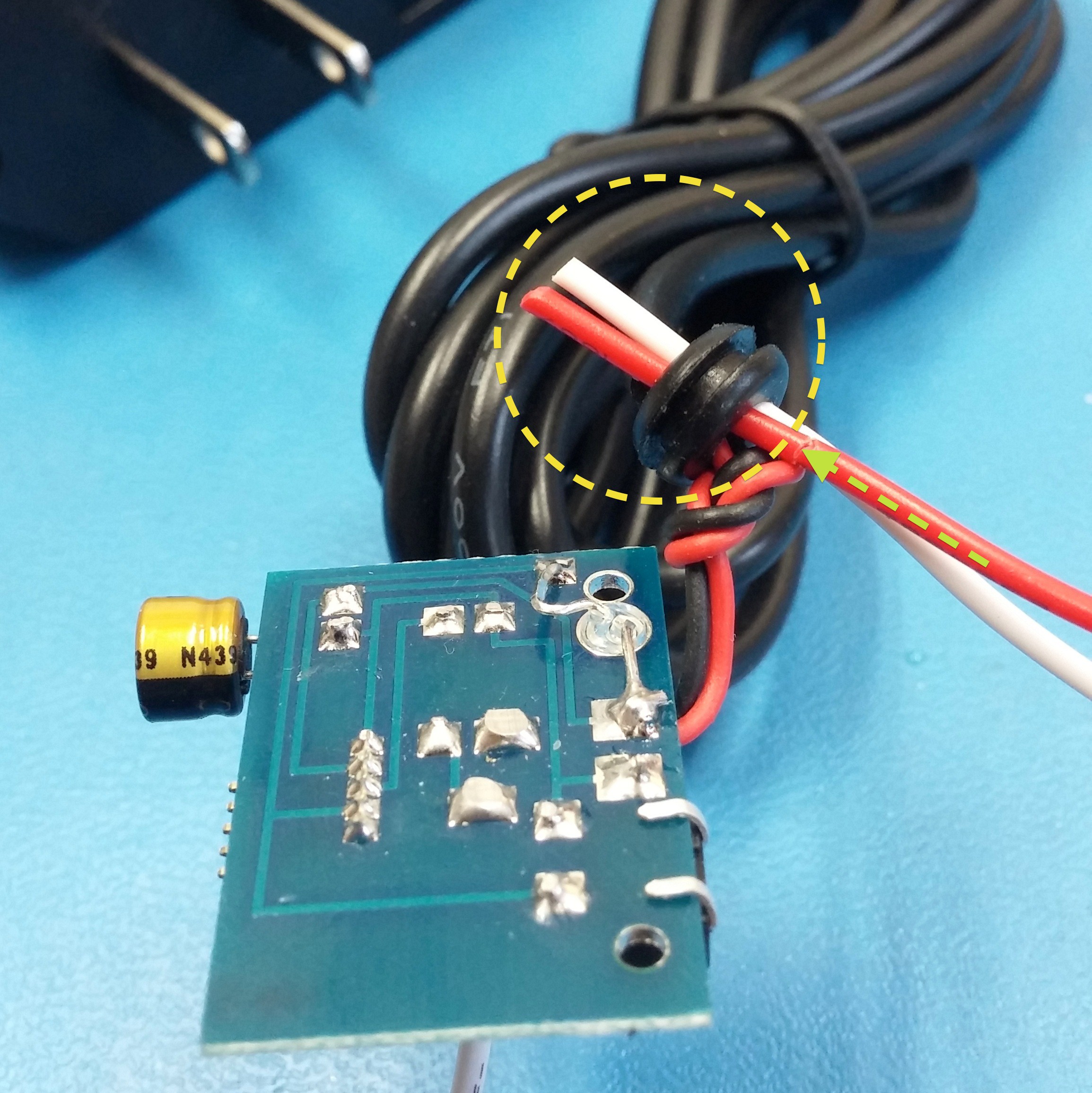
Add Power
Insure the power adapter wires are placed thru the grommet.
![]()
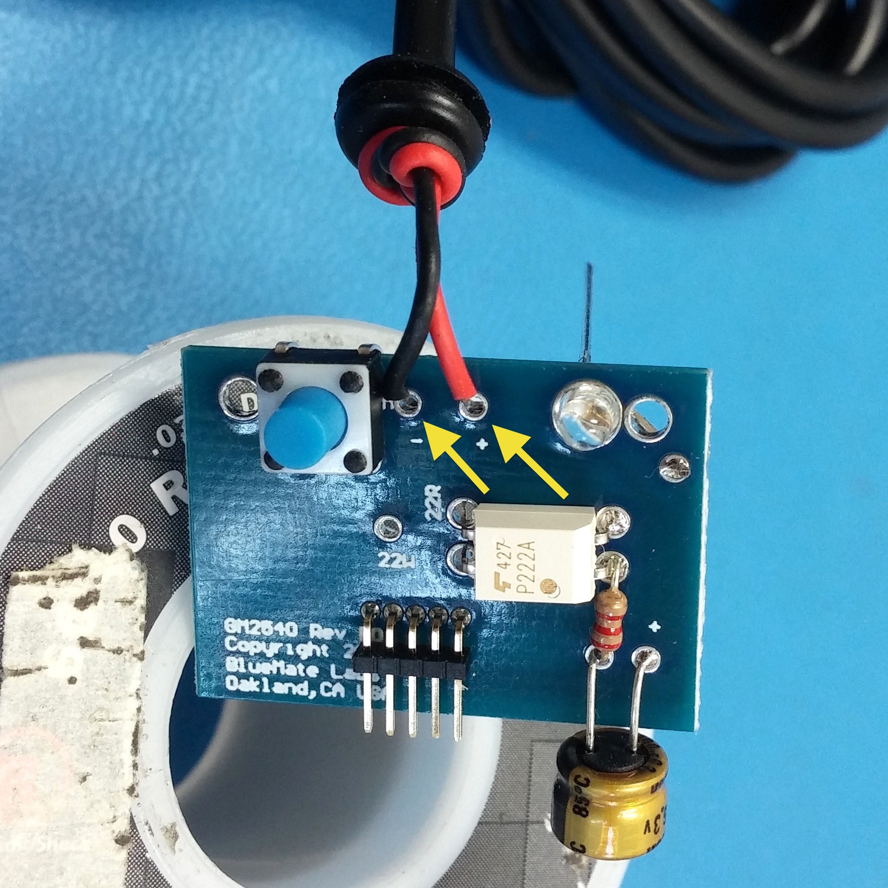
Place the wires from the power adapter thru the top-side of the PCB. Note the holes are marked for red "+" positive and black "-" negative.
![]()
Solder the power adapter wires to the board.
-
8Step 8
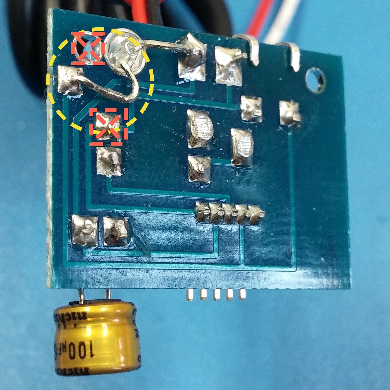
Complete LED
![]()
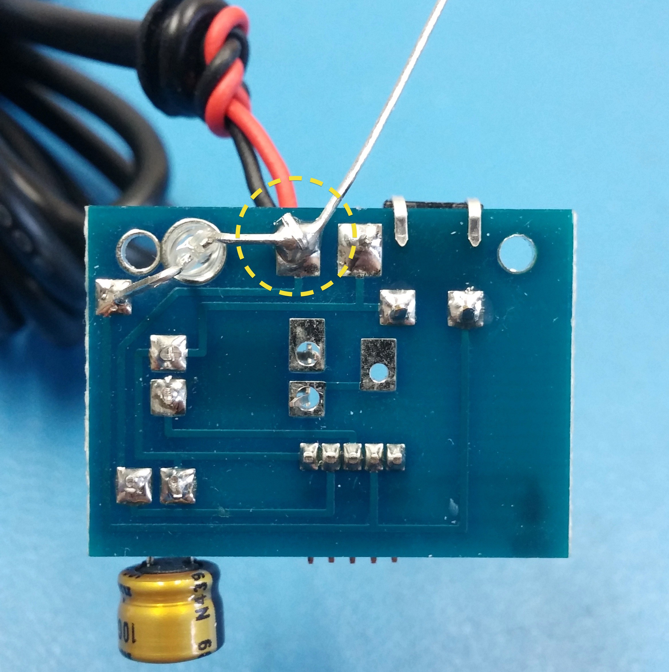
Bend the long LED lead around the positive wire and solder
![]()
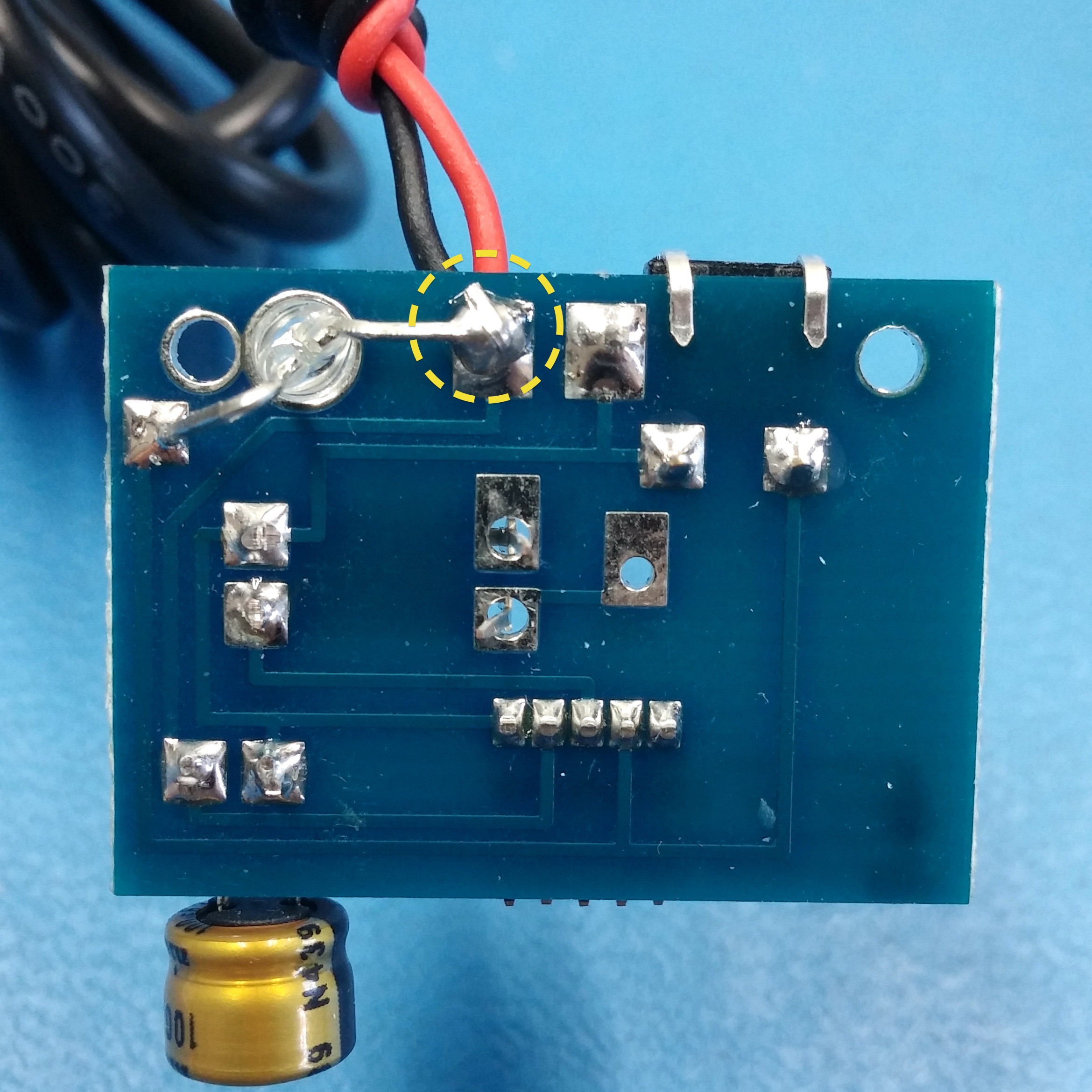
Trim the excess, make sure no wire or solder is touching the neighboring pad.
![]()
Bend the other lead of the LED towards the board. Be sure not to bend it over the screw hole, or touching another pad outlined in red.
-
9Step 9
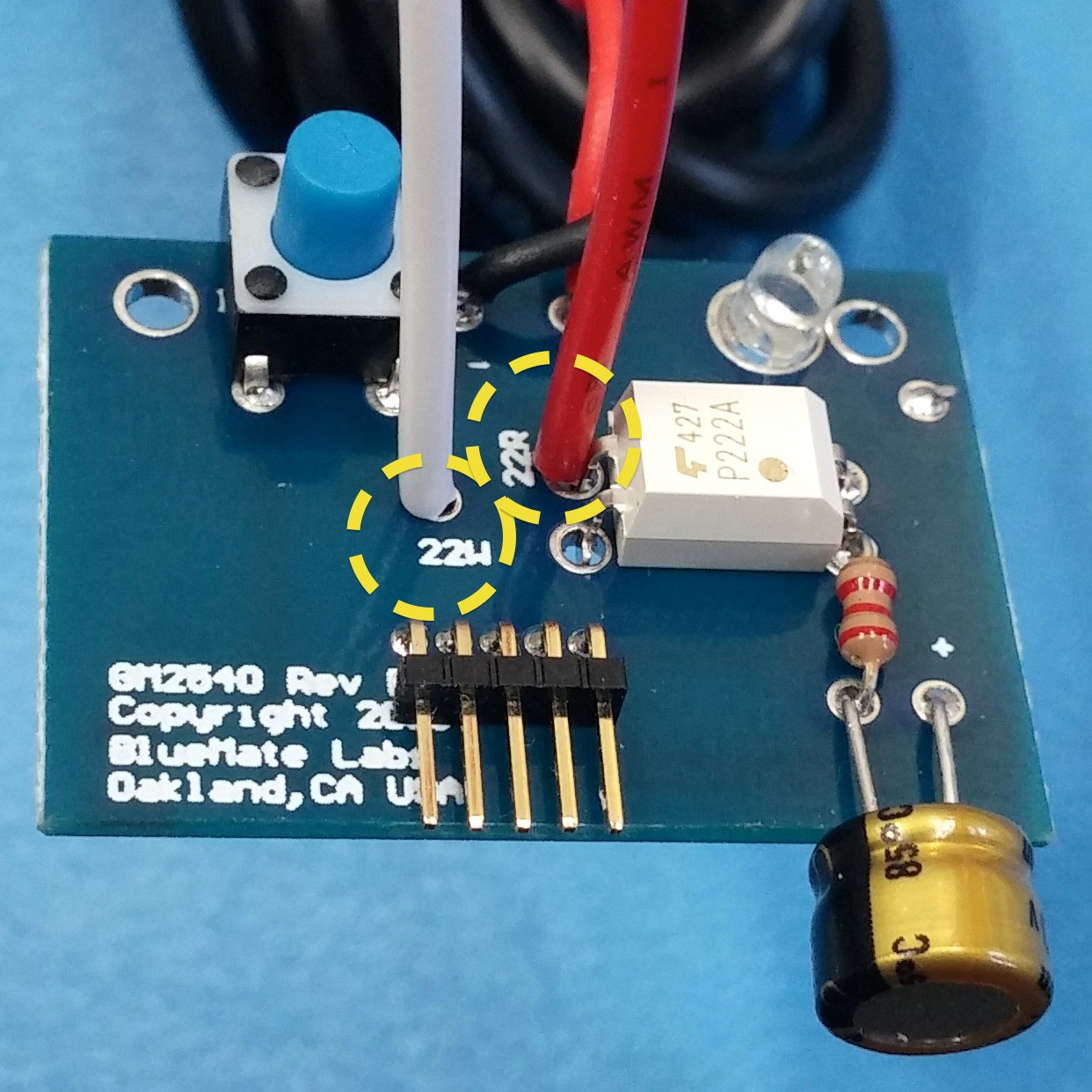
Add Wires
Insert the stripped ends of the white and red wires thru the top of the PCB into the holes marked 22W and 22R respectively.
![]()
Solder the white and red wires on the reverse side of the board, note that the red wire gets soldered along with one of the pins on the "opto". Solder any remaining pins on the "opto" at this time as well.
Push the ends of the wire thru the grommet with the power adapter wires.![]()
When assembly is complete, these wires will attach to and trigger your garage door opener.
-
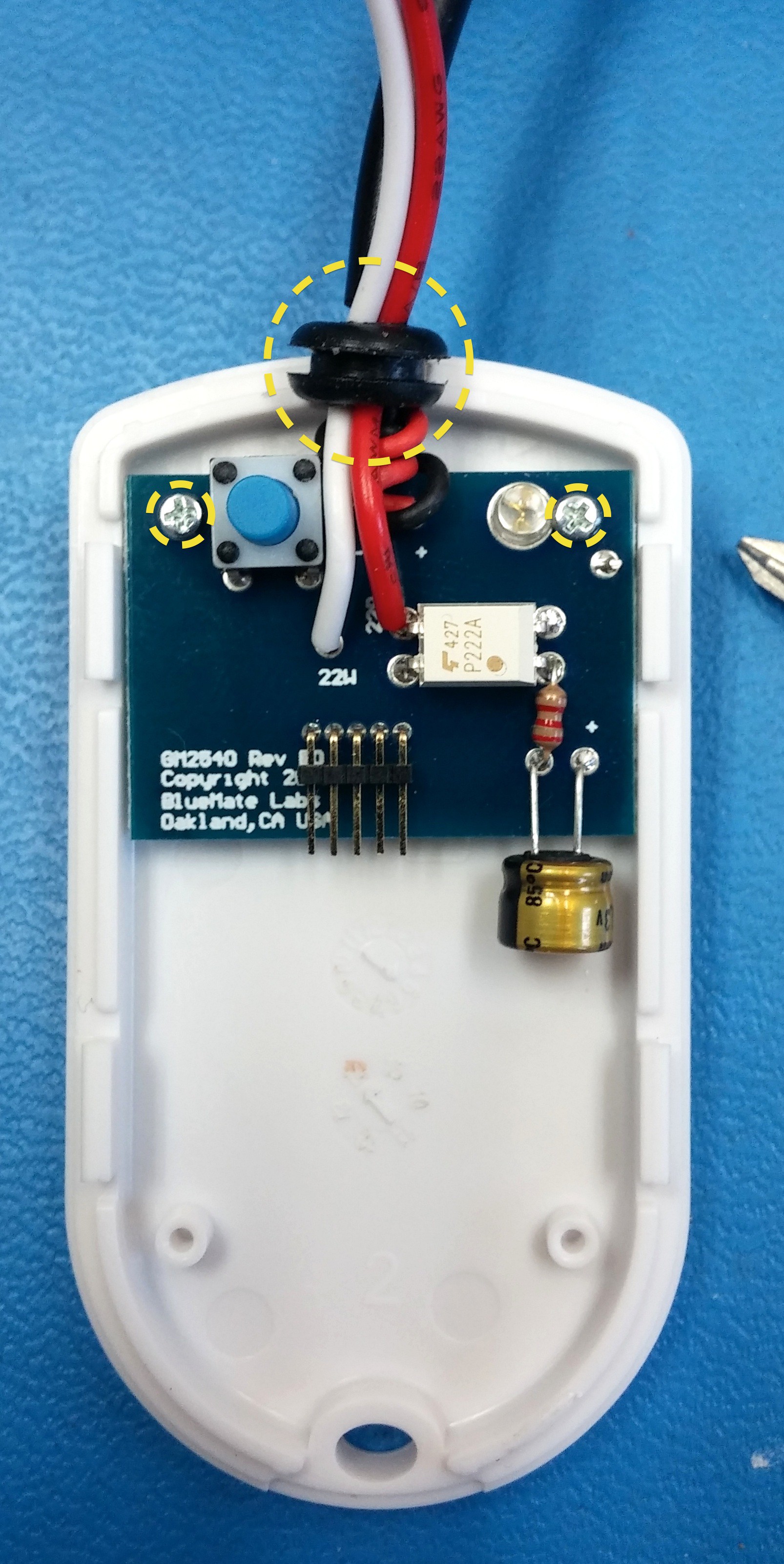
10Step 10
Add Case
![]()
Align the PCB screw wholes with the case, and gently tighten screws. Adjust the position of the grommet to align with the cut out at the top of the case.
GarageMate DIY Kit
Build a receiver to open/close your garage door with an app. Visit BlueMate.com

 Solder just the pin indicated with the yellow arrow, the other pins will be soldered with additional components later. Do not solder all of the pins yet.
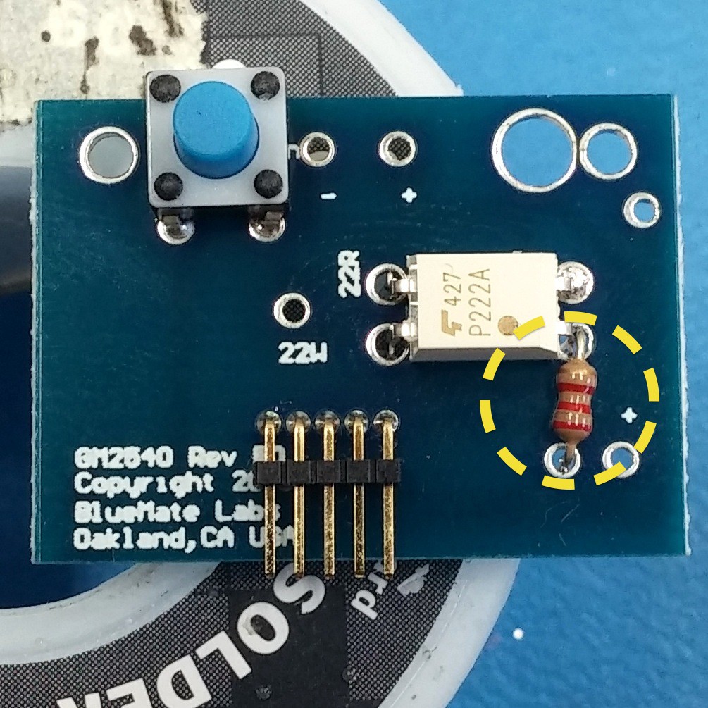


Discussions
Become a Hackaday.io Member
Create an account to leave a comment. Already have an account? Log In.
Hello, I'm trying to do this because I've already bought one bluemate and wish to have another one to my parents home, but my county's customs are way too slow and takes fees on 40% of the total. So I'm trying to build one myself, but it isn't working, maybe because I need to program the Bluetooth module, if that's the case I messed up buying all this components. :
Are you sure? yes | no