 danjovic
Lost two days trying to make the firmware work. It was a good shellacking!
First problem: For updating the controllers I have the following structure:
void Update_Gamepads() {
...
   tmp1=Shift_8_bits();
   tmp2=Shift_8_bits();
   tmp3=Shift_8_bits();
   tmp4=Shift_8_bits();
   tmp5=Shift_8_bits();
   tmp6=Shift_8_bits();
...
...

}
For some reason, the firmware got stuck if I call the "Shift_8_bits()" function more than once. If I called the function only one time was ok.
It took me one day to figure out the most problable cause was a stack overflow. I have replicated the variables and the Update_Gamepads() and related functions in a new project, without the USB code and it worked as expected (as seen in oscilloscope). Since was using the ATTiny45 and despite GCC inform that the amount of RAM usage was below 80 bytes, I've changed the target for ATTiny85 and recompiled the USB project. This time it worked as expected, I mean, no stuck on the Update_Gamepads function.
The other day I spent trying to make the USB to recognize the device. This time the problem was in the USB initialization on the main() function. For some reason I could not define, the code I was using before did not worked. After replacing the startup code with the beginning of code from V-USB project the circuit started to be recognized wy windows, showing the 4 gamepads.
Further enhancement was to synchronize the Updata_Gamepads() function with the end of a USB interrupt. This is necessary because if an USB interrupt occourred during the shifting of the bits, the state of the LATCH line might be changed, and the shift registers would be reinitialized with the parallel inputs, thus ruining the current reading (shifting) of the button states. For doing that I put the code to sleep everytime a new reading is necessary. Then after the next USB interrupt the code follows and a new reading begins. There is a delay of 100us before the reading, to avoid two quick usb interrupts to occour. During this time the CLOCK signal stays in LOW level, which makes the LATCH line goes to LOW level, allowing the shifting of the bits.
if (mustPollControllers())  { // at ~16ms (60Hz)
    clrPollControllers();
    sleep_enable();
    sleep_cpu();
    sleep_disable();     // resume after IRQ
    Update_Gamepads();    // start with a delay of 100us
}
This technique of synchronizing the reading was borrowed from the N64/Gamecube controller to USB converter from Raphnet.
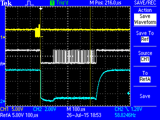
In the picture below the yellow trace is the USB D+ signal, the white trace is the CLOCK signal and the blue trace is the LATCH signal.
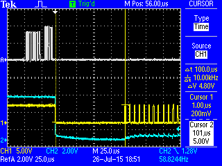
In the picture below the white trace is the USB D+ signal, yellow white trace is the CLOCK signal and the blue trace is the LATCH signal.Notice the 100us interval between the falling edge of CLOCK signal up to the first clocl pulse. Such delay is in the Update_Gamepads() function.
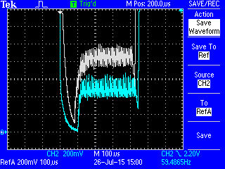
In the meantime while debugging the code I've included a diode (D3) in the RC circuit that generates the LATCH signal for speed-up the falling edge of the signal as well as to keep such level at ~0.5Volts. Without the diode the LATCH line low level was close to 1V. In the pictures below the blue line is the LATCH signal with the diode and the white line is the signal without the diode.

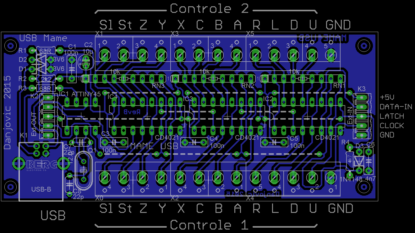
The updated circuit can be seen below.
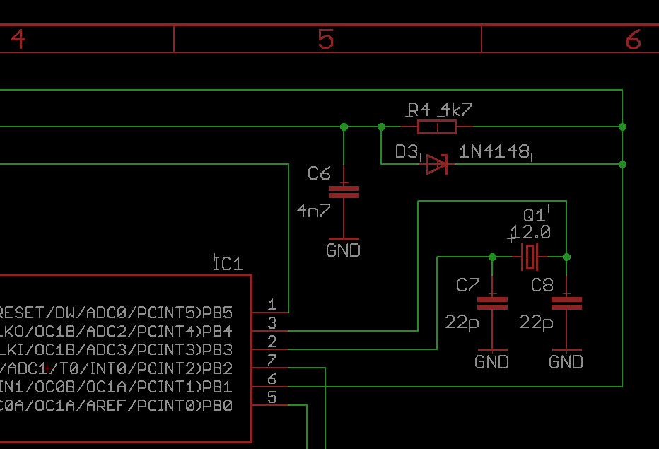
The PCB was modified to include the diode D3. It is at the downright position between the resitor R4 and capacitor C6
Discussions
Become a Hackaday.io Member
Create an account to leave a comment. Already have an account? Log In.