 Daniel Johnson
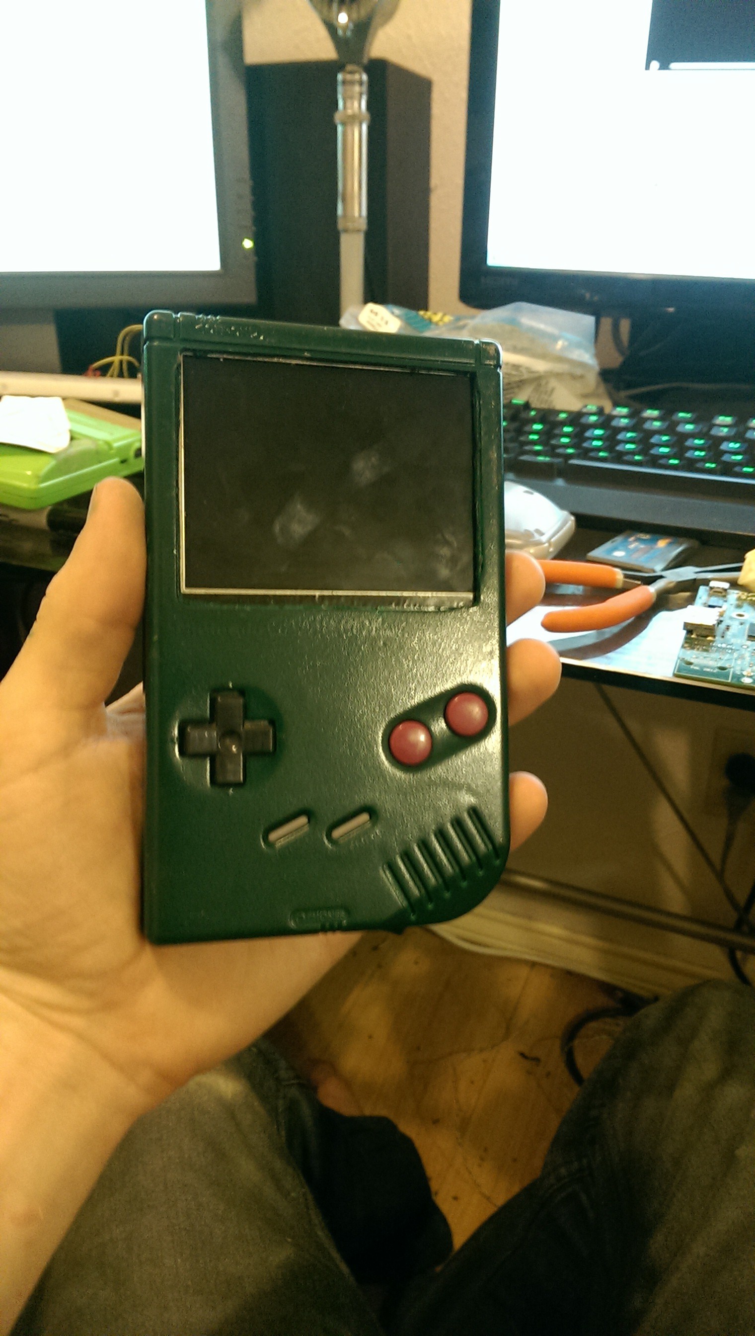
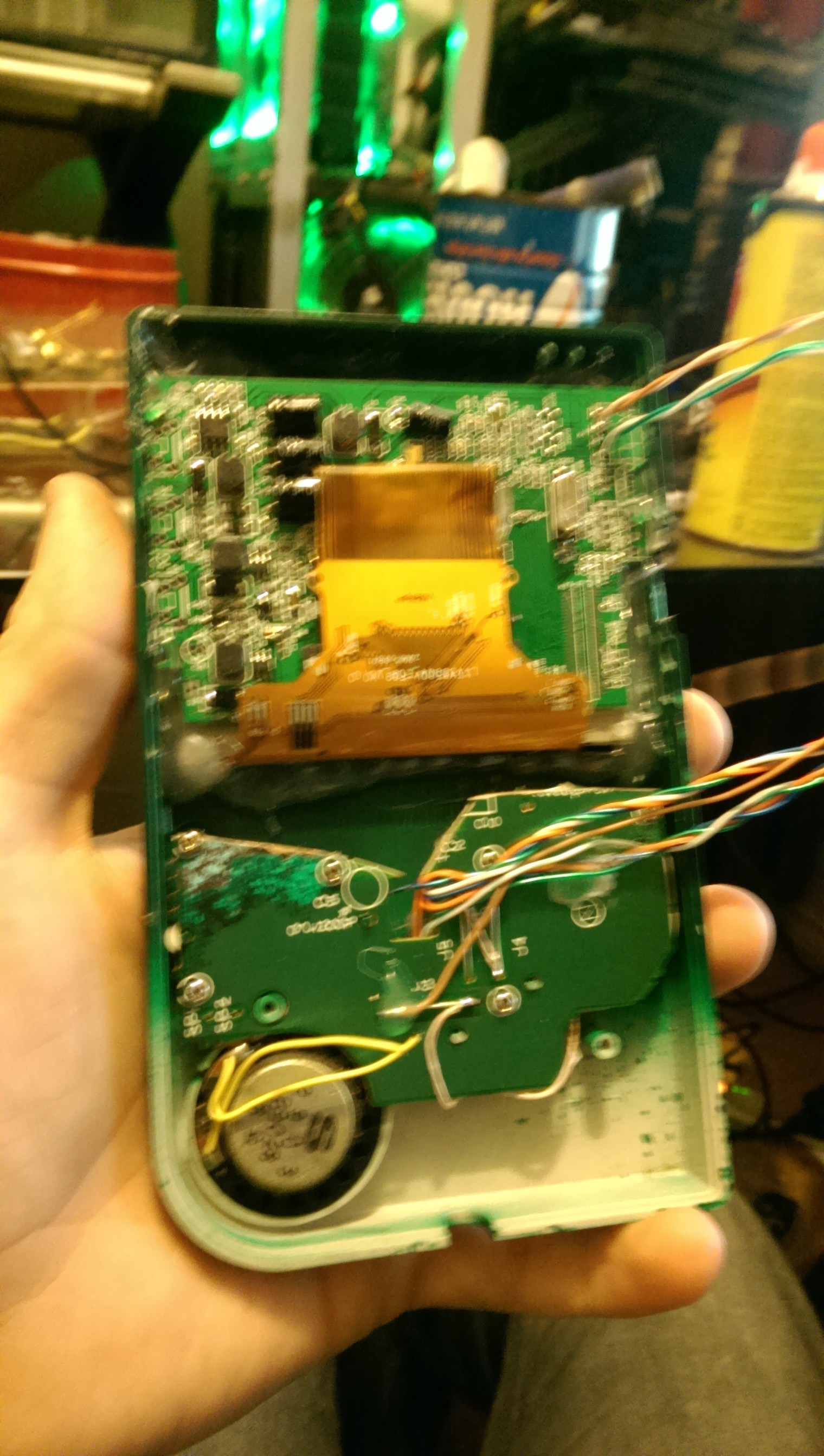
First thing I did was tear down the GameBoy and cut out a larger hole for the LCD to fit in. Then i painted the GameBoy as it was very faded. Then the LCD was fitted. some of the PCB of the LCD had to be trimmed where the tact switches were attached And the GameBoy's PCB screw mounts were cut and ground off. The LCD and PCB were attached with hot glue.
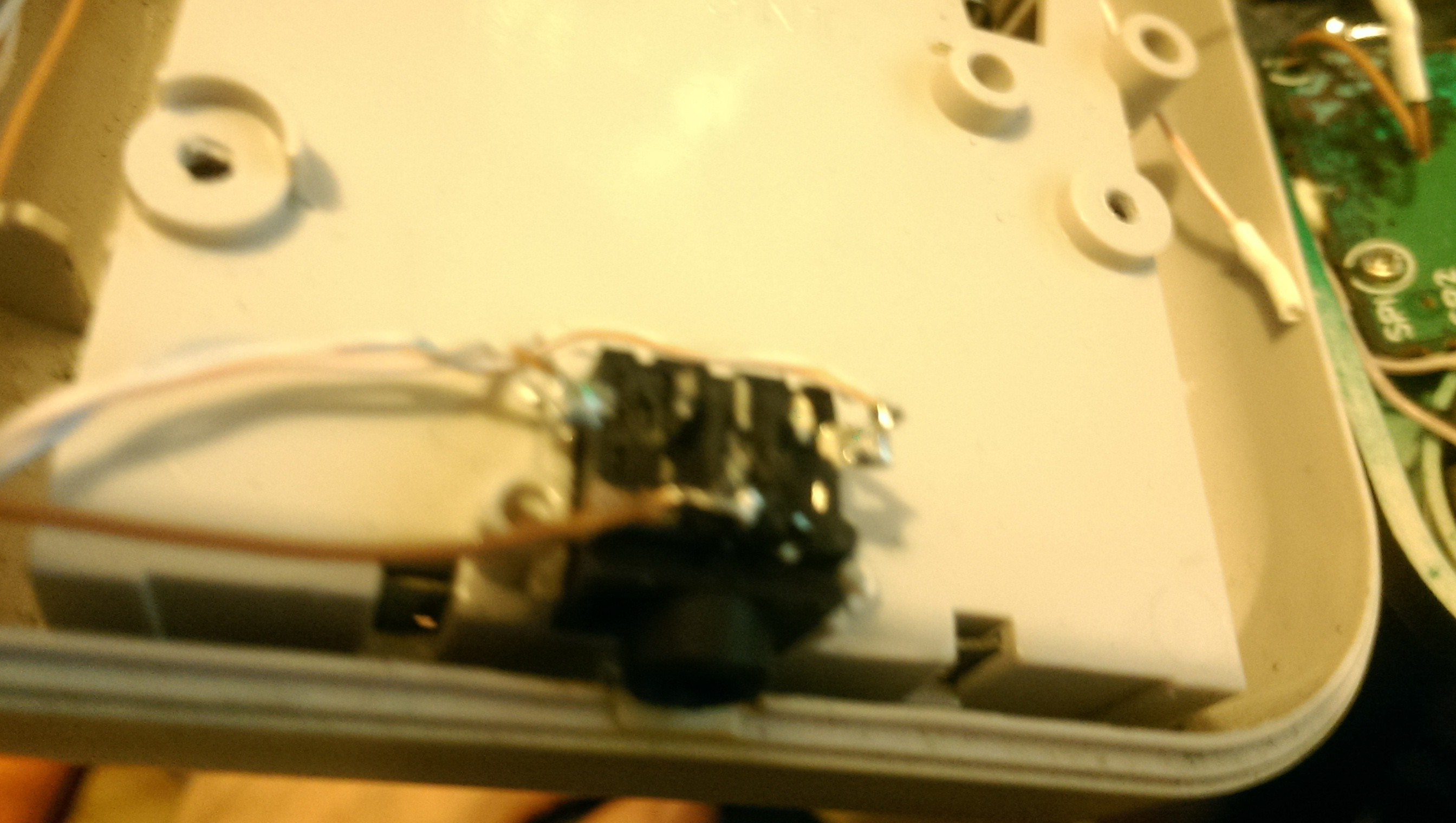
The PCB for the GameBoy controls was cut and places in the PCB were scratched away and wires attached to the traces of the PCB connected with a common ground. this was then reattached to the GameBoy.
(sorry the picture is blurry)
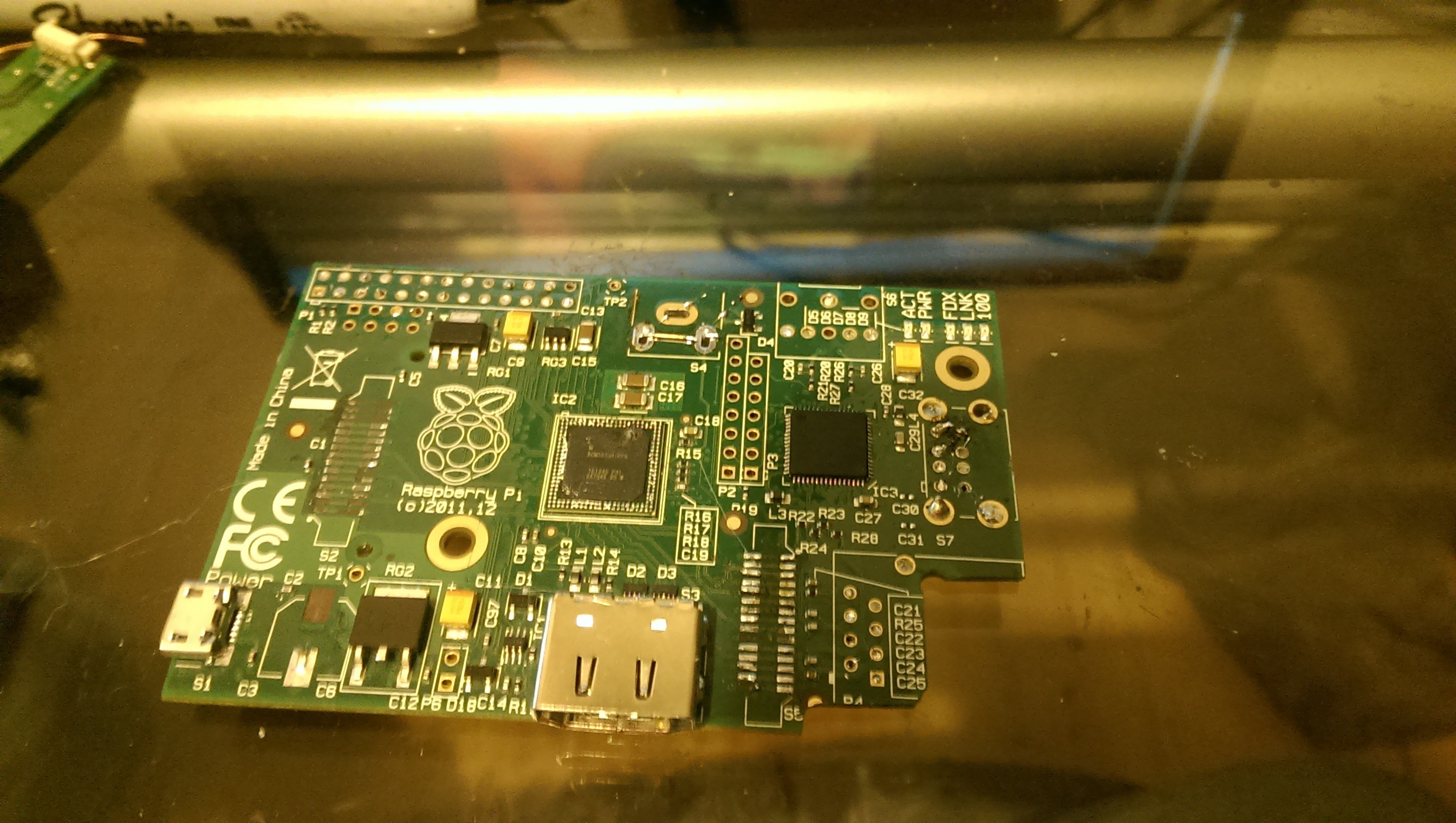
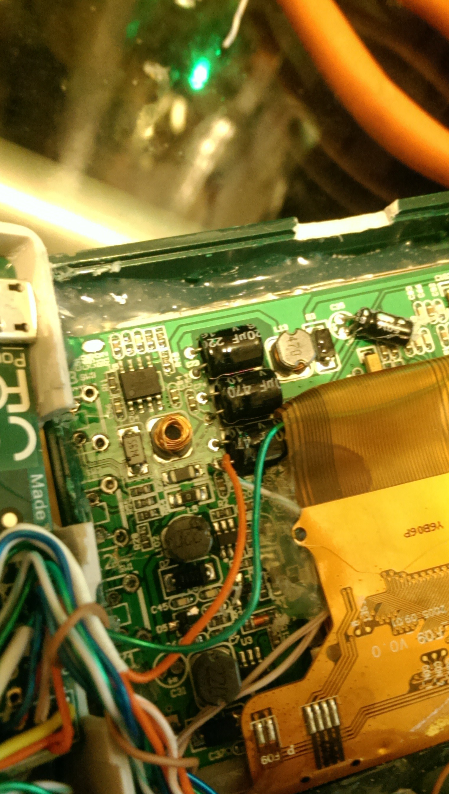
The SD Card, GPIO pins, Ethernet Port, USB ports, Composite Video, and 3.5mm Audio Jack were then removed from Raspberry pi and a section by the Ethernet port was trimmed as there is no traces there and provides a way to hold the case together later. Also capacitor C3 was removed as it is not needed for how it will be powered later.
 (This is the PCB that I accidentally powered with 12v and fried. It is notched more by the ethernet and the camera and LCD flat flex connectors are removed)
The SD card was then wired up to some wires and hot glue was placed over
the wires to brace them and keep from lifting the pads. Note this is
the first time I wired the SD card. later, only the required lines were
wired. GND and 3.3V was attached at the GPIO instead since that provided
better support for the wire, and the SD card inserted switch was
bridged and the read-only signal was left disconnected as the raspberry
pi does not use it.
The controller was then attached to the GPIO pins and the composite video is connected to the Raspberry Pi and LCD.
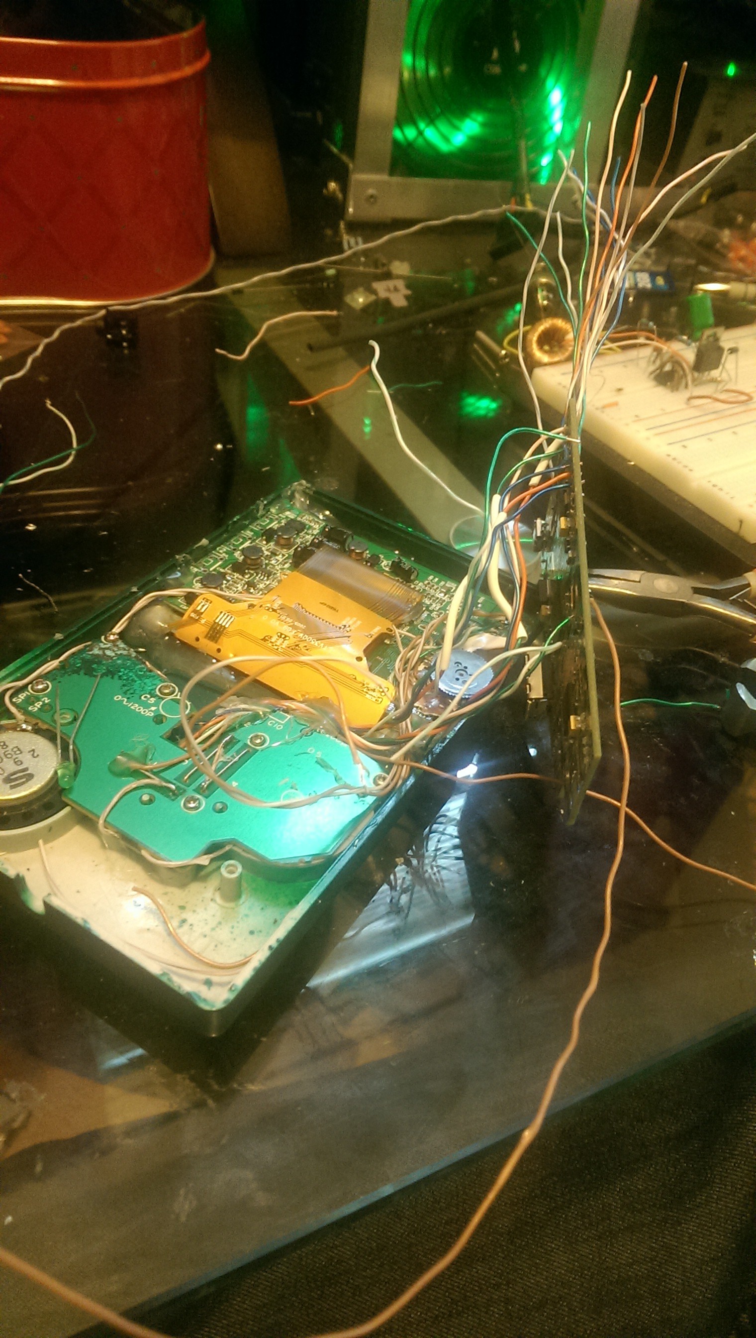
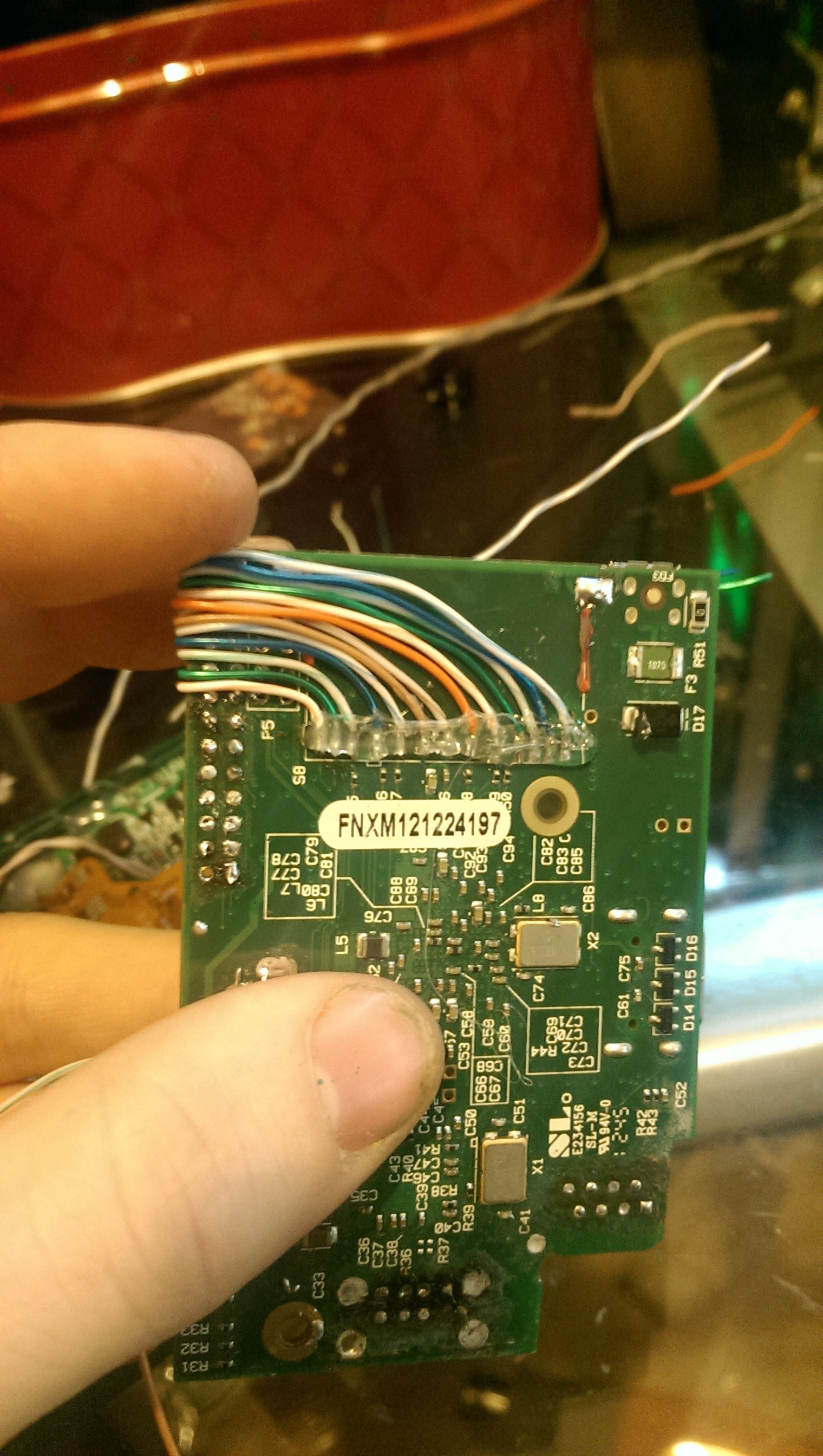
The SD card wires were then attached to the cartridge connector. Note that this is the first revision of the Cartridge pinout.
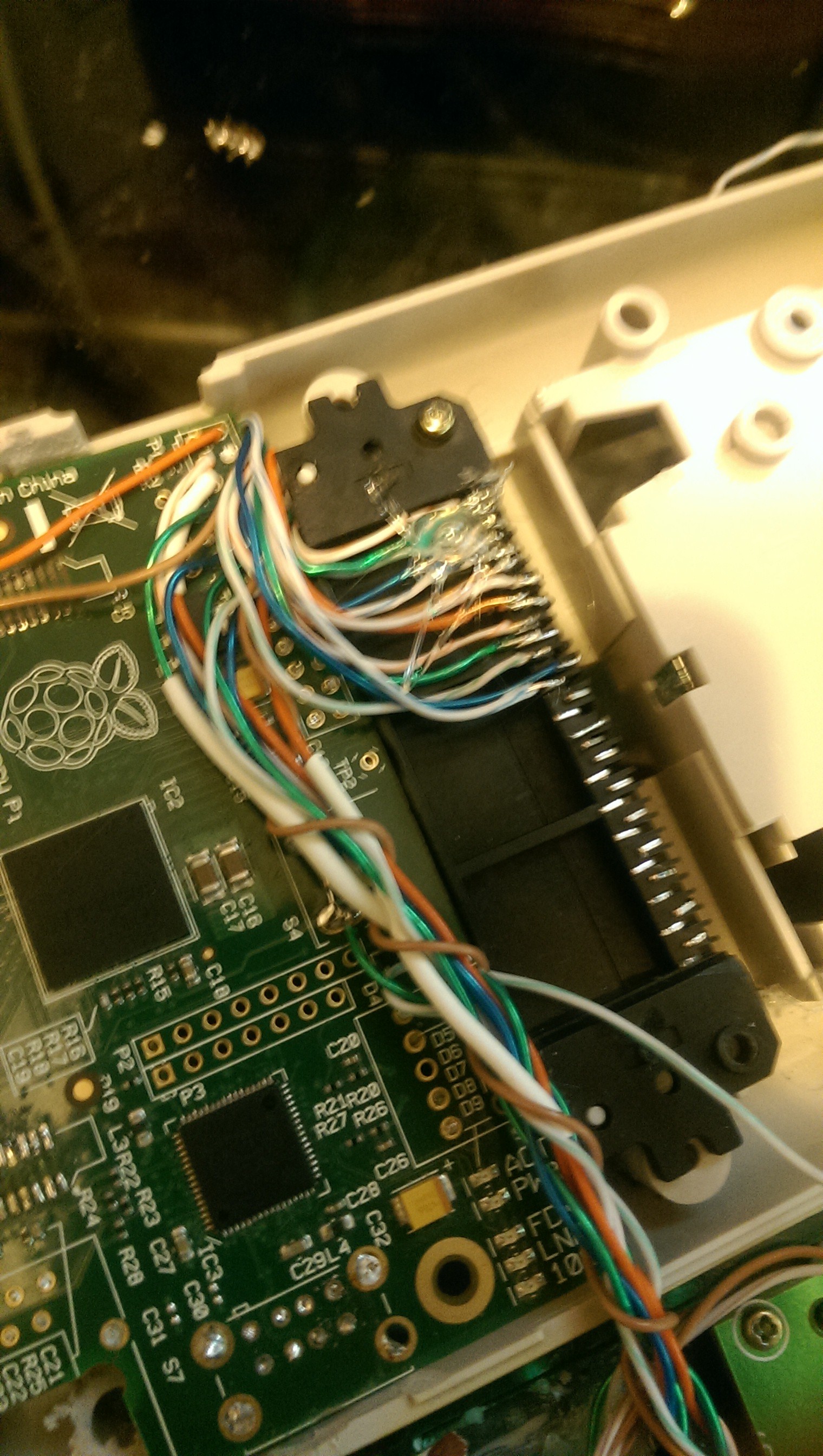
The ethernet pins 1-6 were then attached to wires and connected to the cartridge connector. Only pins 1-6 are used because the raspberry pi is not using gigabit ethernet or power over ethernet. The usb pins 2 and 3 were connected after as the cartridge will already have a 5v+ and GND. The GameBoy was also cut so the HDMI port can be accessed from outside the GameBoy.

Revision 2 of the cartridge connector pin-out uses less pins and is much more reliable. The power wires, 3.3V 5V and GND, use 2 pins to provide a reliable connection. The SD card pins are alternated with the ethernet pins as the cartridge alternates position of the pins and the further forward pins made a more reliable connection so the SD card was attached to those pins as that is a critical component whereas the ethernet is not as critical. The same is done with the USB ports, one USB port is on the top pins and one is on the bottom pins. Because it uses less pins it also allowed me to not use the last 5 or so pins as these were damaged because this GameBoy suffered from an acid leak. It can also be seen that the contrast port has been used for a volume control for the speaker. this is still yet to be attached to an amplifier and used.
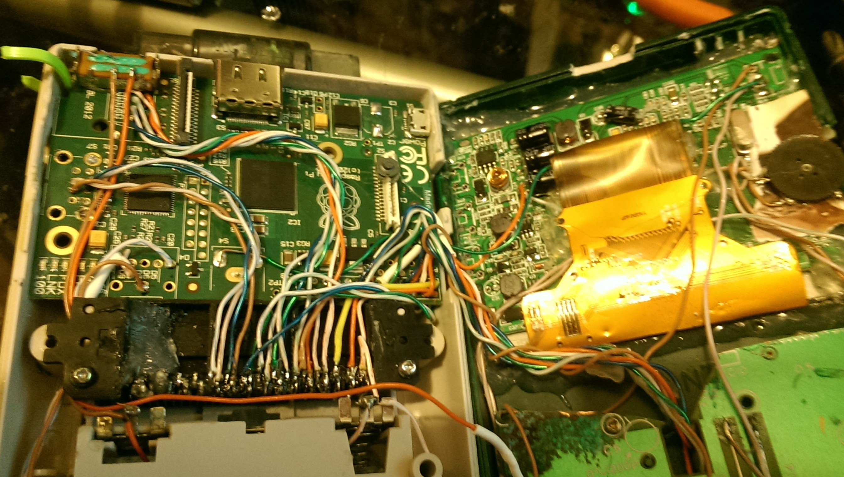
The GameBoy's switch was de-soldered from the board and hot glued at the top of the GameBoy and attached between the battery and the LCD. You can also see where a zip tie is used to keep the top of the GameBoy attached together.
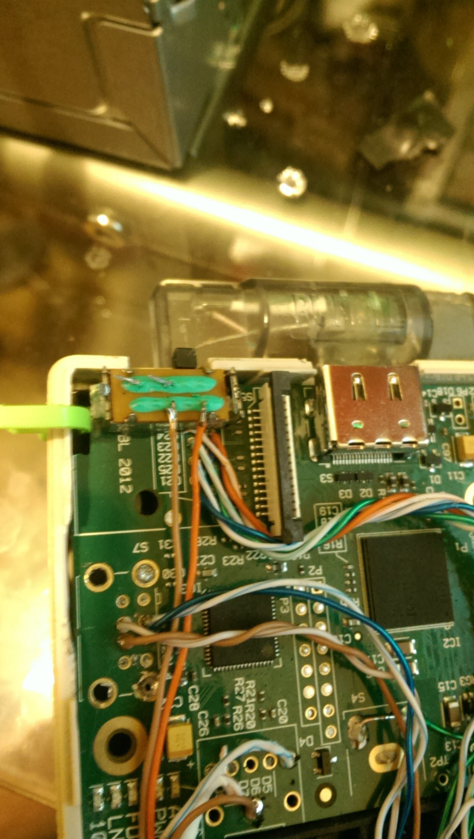
The headphone jack from the raspberry pi was relocated and fits perfectly where the GameBoy's original headphone jack was mounted.
Originally I had planned to find a 4AA battery to 5V regulator but such a thing does not exists because the voltage of 4AA varies between 3-6V which makes it difficult to regulate to 5V. So I ordered a 3-9v step up to 12v converter to feed the LCD. This didn't work as the raspberry pi and the LCD draw too much current for the step up converter to work efficiently (No I did not connect the pi to the 12v regulator to burn it out. i burned it out on my voltage supply by not paying attention to what I had it set to). One of the great tricks i found and used was the fact that these LCD's actually regulate a cars 12V to 5v anyway. most people use this trick to power the LCD from 5V. Instead I used it as a voltage source for the raspberry pi since the LCD uses a more efficient buck converter instead of a LDO 5V regulator that wastes this energy in the form of heat. Conveniently the LCD's input voltage can operate as low as 6v. I don't know what the maximum tolerance is but I'm not going to try and find out.
This input voltage makes it PERFECT for a 2 cell lithium battery. Because i didn't want to remove the GameBoy's battery compartment, I decided to use 2 14500 lithium 3.7v batteries. These are roughly the same size as a AA and since 2 of these batteries in series allows for a voltage discharge range of 6v to 8.8v it makes it ideal to use as a power source. since there are 4 AA slots in the GameBoy's battery compartment I will be wiring the batteries 2 in parallel and 2 of those in series in order to increase the capacity. with some of the 14500 batteries having a 2400mah rating the power source can have a supply of 4800mah and since the Pi and LCD take roughly 800ma this source could last up to 6 hours.
This seems to be long enough for 1 project update. in the next update i will go over the build of the cartridge(s) and will have another update for when i add the joystick. I may also add a detacheable XBOX 360 chat keyboard in the future as well. For now, here is a video demo
Discussions
Become a Hackaday.io Member
Create an account to leave a comment. Already have an account? Log In.
Sure thing. That'll be the next thing I go over in the next update. In short I used the RetroPie distro and for the GPIO input I used an actual driver someone made. http://www.newsdownload.co.uk/pages/RPiKeypadDriver.html I like this driver cause it will actually let me do analog input for the joystick.
Are you sure? yes | no
Can we get more info about the software side of things, please?
Are you sure? yes | no