 Alpha Charlie
Here is the basic circuit I used to create my own pitch clocks for 4 of the output channels. The TI CD40106 runs the 4 oscillators. Each has it's own potentiometer. The capacitor for each oscillator should be adjusted to taste for the channel you are modding so that the pitch variation is noticeable and pleasing to the ear when the potentiometer is turned...
(Note - In the drawing below, the switch numbers are transposed on the right hand lower side... 3 should be above 4. Ooops!)
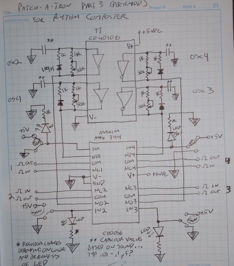
The four oscillator signals run to the NO connections of the 4 switches in the Max394. The NC connections of each switch are connected to the actual Roland TR-626 pitch clocks signals on the gate array(IC 13). The COM are connected to the clock inputs on IC14 of the TR-626. This allows me to choose between the Roland clocks and my pitch modded clocks with the four spdt switches.
* The value of the resistor connected to each LED will depend upon the diode forward voltage and current for the LED. 150-330 ohms is typical. (there's a calculator you can use here if you know the specs for your LEDs.)
** The value of the capacitors for each oscillator will be dependent upon the clock signals you are replacing and how far you wish to bend them... the frequency out will be around 1/1.2*RC (just count the 500K pot and the 1k. Ignore the diode/1k leg in the freq calculation. It's just there to keep the pulse width low on the generated signal. The Roland clock is not on a 50% duty cycle. It generates fixed width pulses...) For the caps themselves I use polyester or mylar. I started with 0.1uF and adjusted from there by ear. USe a larger capacitor for a lower pitch, a smaller capacitor for a higher pitch. To limit the highest pitch reachable on the high end, you can increase the 1k resistor connected to the pot to 3.3k or 4.7k. The pots are 500k, If you can find them use reverse logarithmic pots. Linear will work in a pinch but adjusts the frequency linearly, which is not how humans perceive pitch.
If you decide to try this mod- Be Careful! Installing this circuit in the Roland is a nightmare. It was 100% the most difficult part of the entire project. Both IC13 and IC14 are SMT chips and doing this mod means either desoldering one of them or cutting traces on the board. Neither option is easy. Below is a video showing the mod. You can see what I mean.
Also- unlike the Patch-a-tron which requires minimum tools to construct, an oscilloscope is almost required to troubleshoot this mod if anything goes wrong.
Discussions
Become a Hackaday.io Member
Create an account to leave a comment. Already have an account? Log In.