 chrisprattmt
I needed to remove the dials and the switch from the board because I wanted to have them accessible from the rim of the ear muff. However, each of these components had a minimum of 5 pins. My approach was to use a hot air gun to melt all the solder on the board while it was lifted in the air with a helping hand stand. I then pulled out the component whenever I saw all the solder was melted (very carefully) with tweezers. This technique worked perfectly and barely damaged the plastic components.
After soldering the proper length wires to each leg of the component and then to the proper pad, I began to cut slots out of the edge of my plastic ear muff for the dials to be mounted later.
My next task was to make the headset disconnect-able from the cable. I did this by salvaging a female Ps2 connector from an old ITX motherboard and a male Ps2 connector from an old mouse that was lying around. I cut open the Ps2 connector with a razor blade, snipped most of the glue aways and melted all the internal glue with a hot air gun so I could shovel the rest out with a pair of tweezers. This allowed me to get to the pins of the connector. I then took the headset cable (which needed 5 pins for power, ground, left signal, right signal, and mic) and soldered it to the bare connector and reversed the process – putting hot glue around wires and gluing the Ps2 connector sheath with super glue.
I easily mounted the female Ps2 connector into the headset in a large cutout hole with super glue and hot glue .I also colored both connectors black instead of that teal color.
I once saw the mic-mute indicator light (red) and mic-on indicator light (green) on the tip of the mic on higher quality headsets so the user knows for sure if the mic is muted or not with his peripheral vision. I wanted this feature - so I ran some tiny paint coated transformer wire down the mic arm and into the tip of the plastic mic housing – which I cut a hole in and embedded the LEDs in hot glue and then glued the blob to the plastic housing so they could be seen. ( I ran the LED ground lines to the mic ground line.)
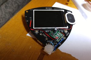
Next, I glued the corners of the amp board to the plastic ear muff housing and also hot glued the dials and mic mute into their proper place on the rim of the plastic ear muff.
My last feature that I needed to do was bypass the amplifier so I could use the mic and headset on a cell phone. They clearly say in the description that this headset will not work without 5v USB power (but i say: "nay nay") I did this with 2 double pole double throw switches. This allowed the left and right signal to bypass the amplifier completely and go right to the speakers. However, the ground the speakers used needed the amplifier to be powered in order to work (signal ground :/ .) So, I used my other switch for bypassing the amp board with the mic and switching the ground for the speakers from signal ground to common ground (which the mic and amp board used.) My engineer colleague had supposed having the speakers and mic on the same ground would cause interference. However, over the past 24 hours of use and with the long phone call I made – There was no interference on my end or his (WIN!) However, if I want to use the amp board for full functionality with the dials and boosted bass – I need to switch everything back by flipping the switches or there will be no sound. I drilled snug holes with a cordless drill and super glued the switches in place. They hold very firm.
My final project now (which the parts are in the mail) is to make another cable for this headset that isn’t 16 feet long…. I want one that is 4 feet long for easy on person carrying that has a 4 conductor 3.5 mm jack so that I can call people and use it while I drive.
Conclusion – without the amp the quality of the music is still amazing – this headset has excellent fidelity for its price (about 30 bucks refurbished.) However, the bass isn’t near as powerful and the mids aren’t as strong either as when I have the USB connector plugged...
Read more »
 Todd
Todd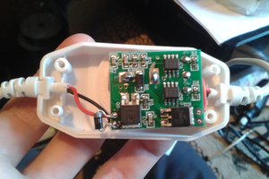
 Arya
Arya
 Patrick
 Thomas