 TAIBHSE DESIGNS
3D Printing
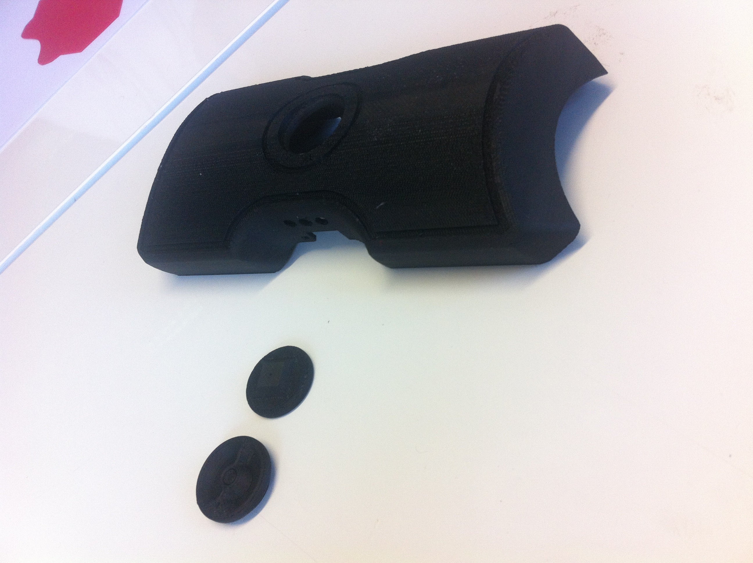
We had two options for creating the shell and dial for the prototype, we could 3d print them or we could model them carefully by hand. We only had 2 weeks before the deadline so we settled on 3d printing in hopes of having the parts ready faster, it took us 3 days to get the parts printed at the cost of around €40 (or 44.40 us dollars as of writing this). The remaining week was spent sanding the parts down to get a perfect smooth finish, though despite the printed parts being black we decided to spray them with a black paint in order to get a slight gloss look similar to our keyshot renders.
Repurposing Materials
After we had the shell and dial 3d printed, we needed rubber, elastic and foam. We went to various local shops to pick up supplies, we got the rubber in red from a non-stick baking mat we found on one store (this later proved a problem). The elastic proved difficult to find until we were passing through a clothes section and saw a pair of mens boxers (briefs) with black elastic and red trimming on them that matched the red of the elastic, we quickly bought them as a size large in order to get more of the elastic for the price given a size small was half the size at the same price, we went for large. For the foam we intended to make a soft cushion instead for the prototype, so we bought cotton balls to use as stuffing and a silky female top to cut up and use as material as it was soft and felt really nice to the touch.
Working with Rubber
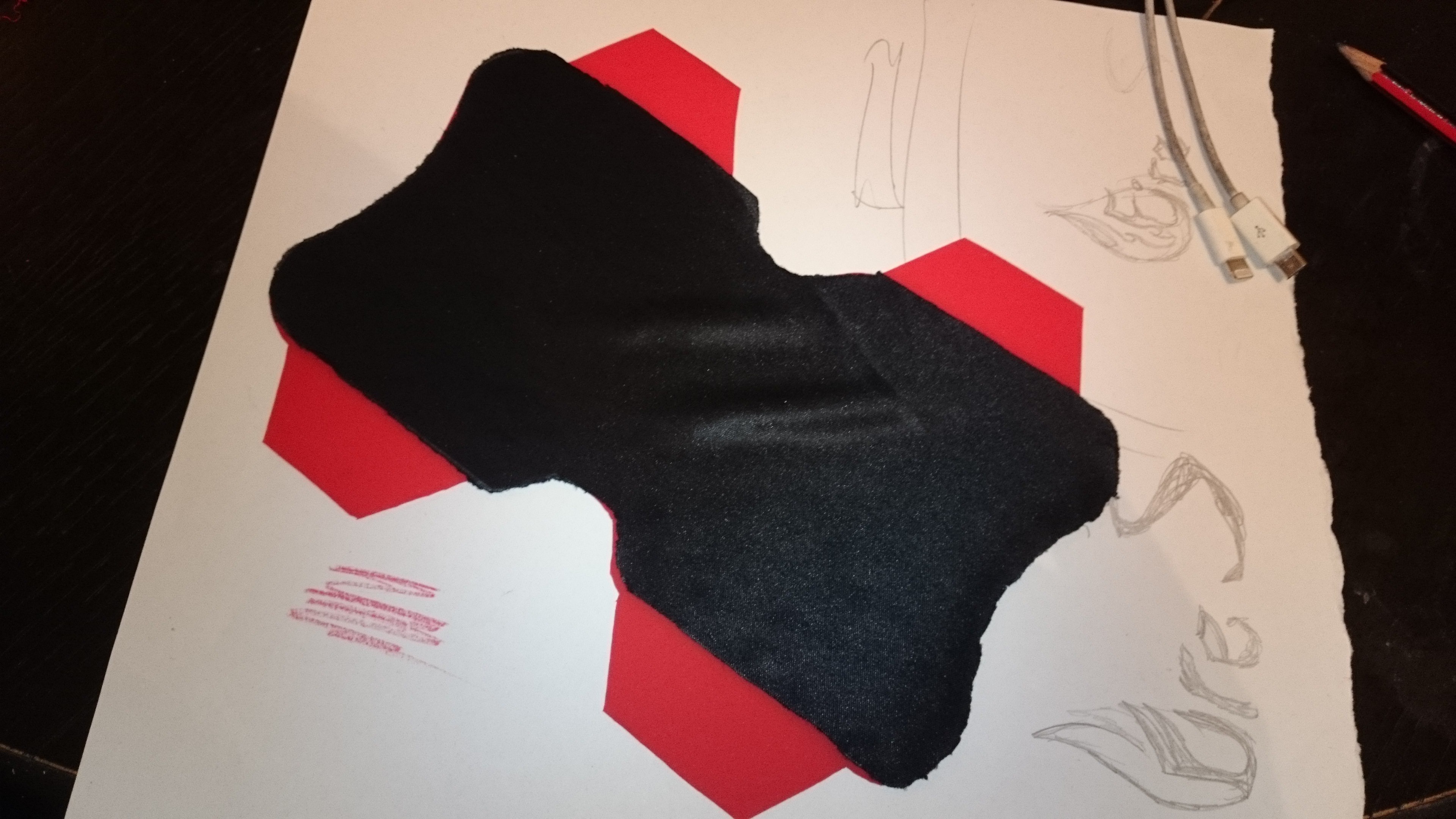
We had two sheets of the rubber bought as a precaution, we later were thankful for this decision.
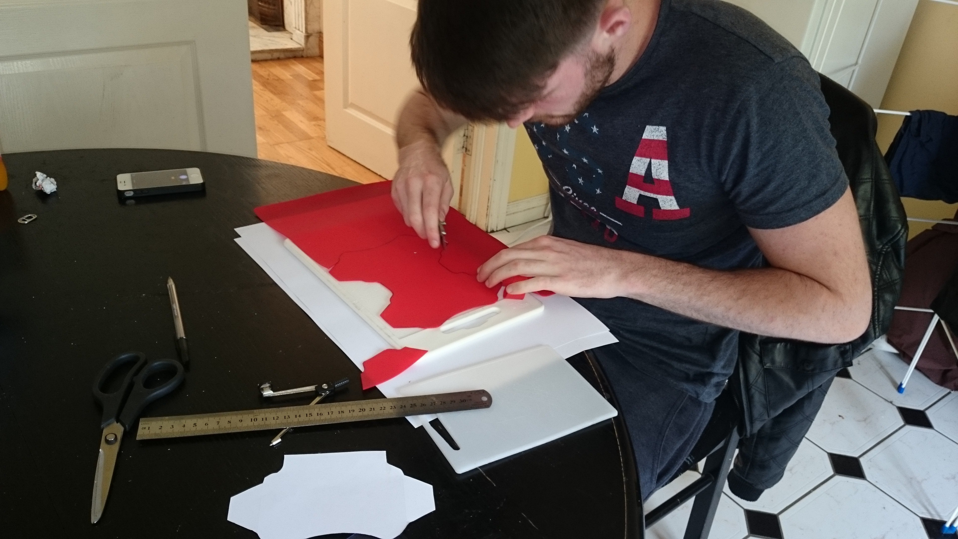
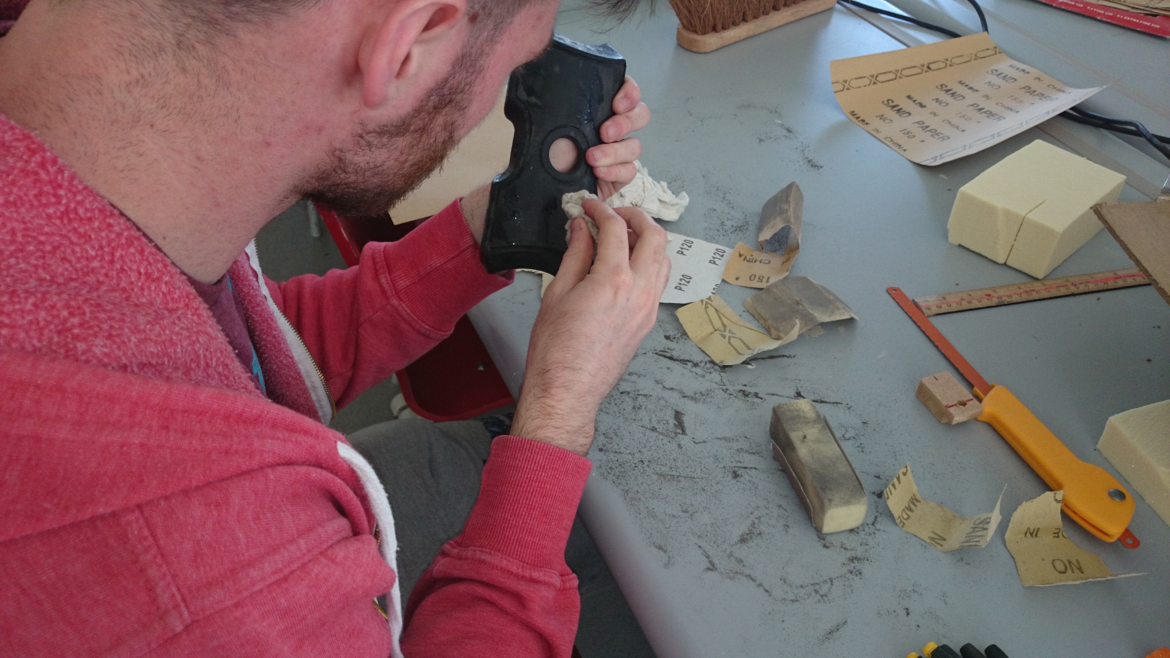
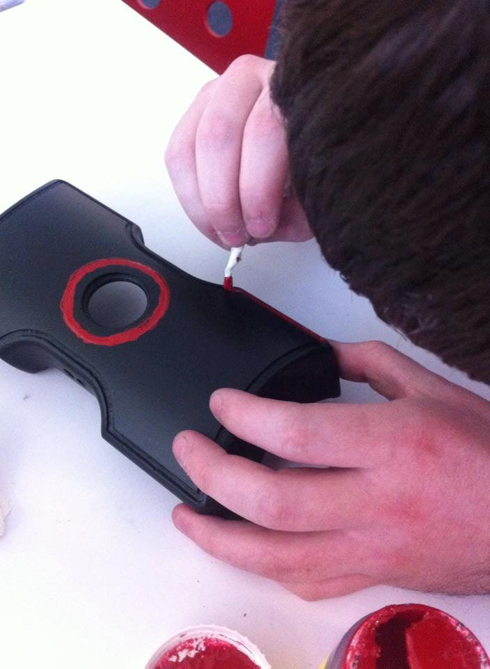
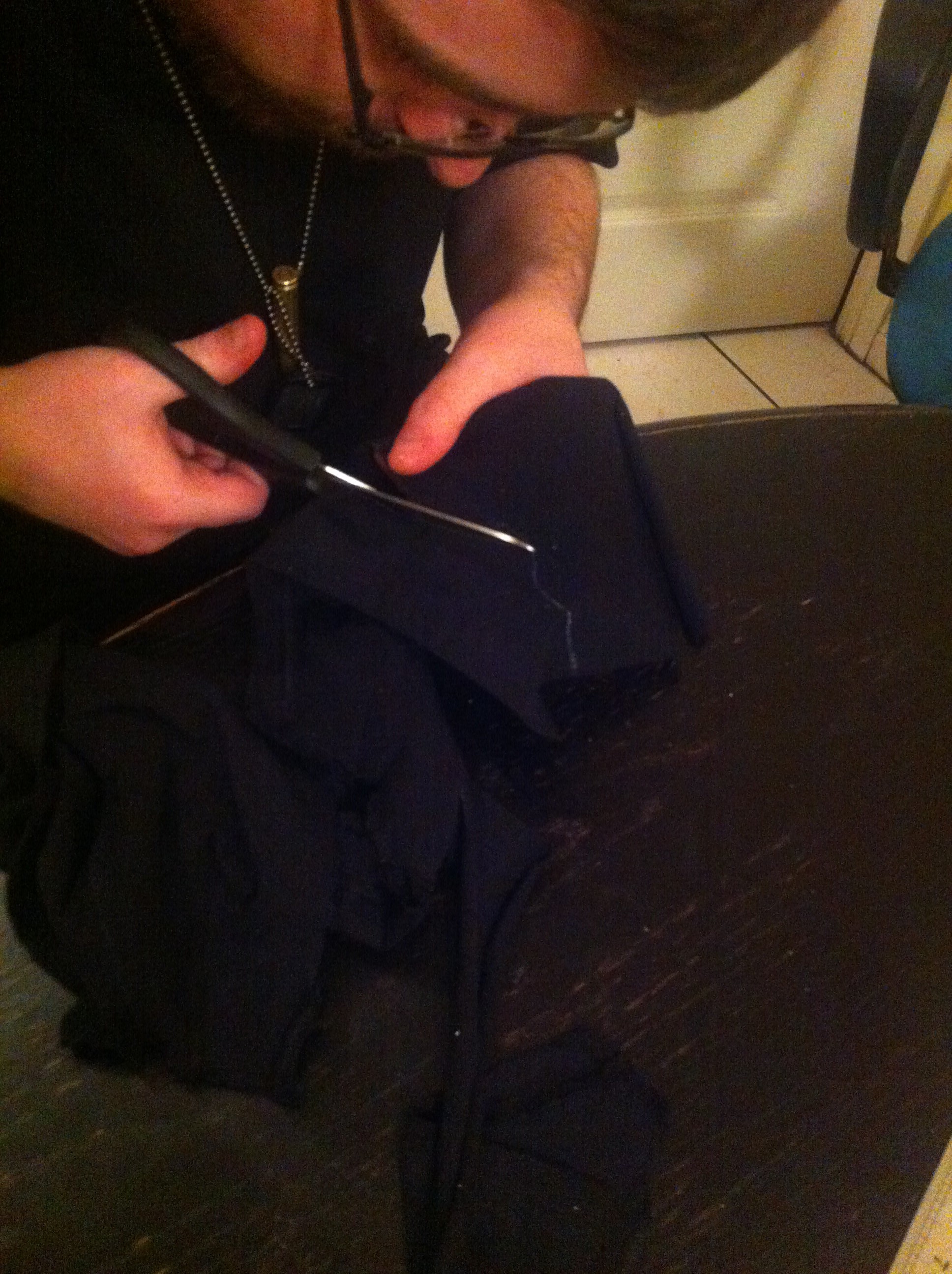
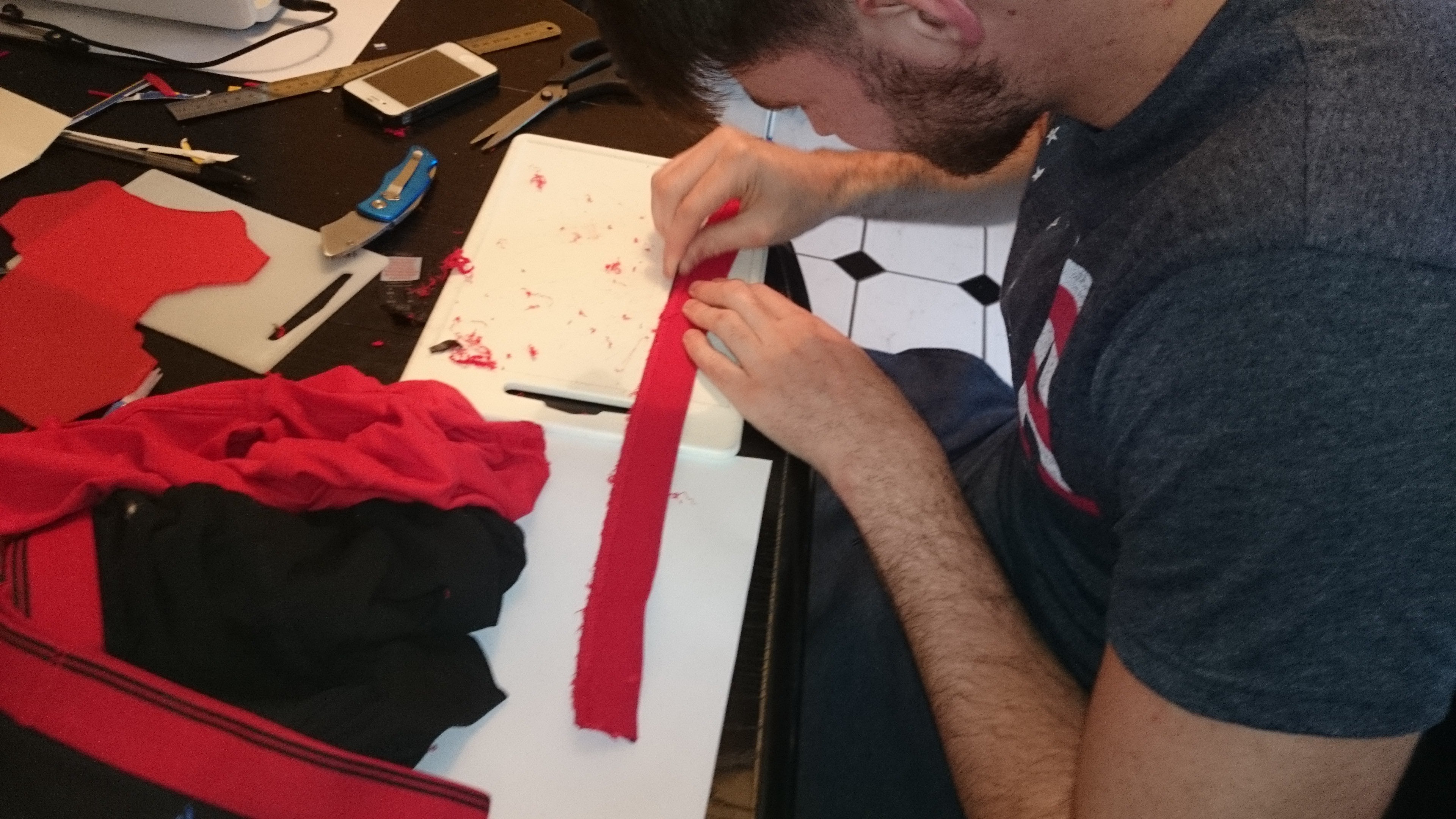
Pictured is Tomas cutting out the rubber. The shell was traced out onto the rubber using pen and then 4 extensions added where the elastic would be attached. When later fitted with the shell it had some issues due to the curving causing the rubber to be slightly smaller than needed. We fixed this by adding a 1cm extension to the tracing on the second attempt.
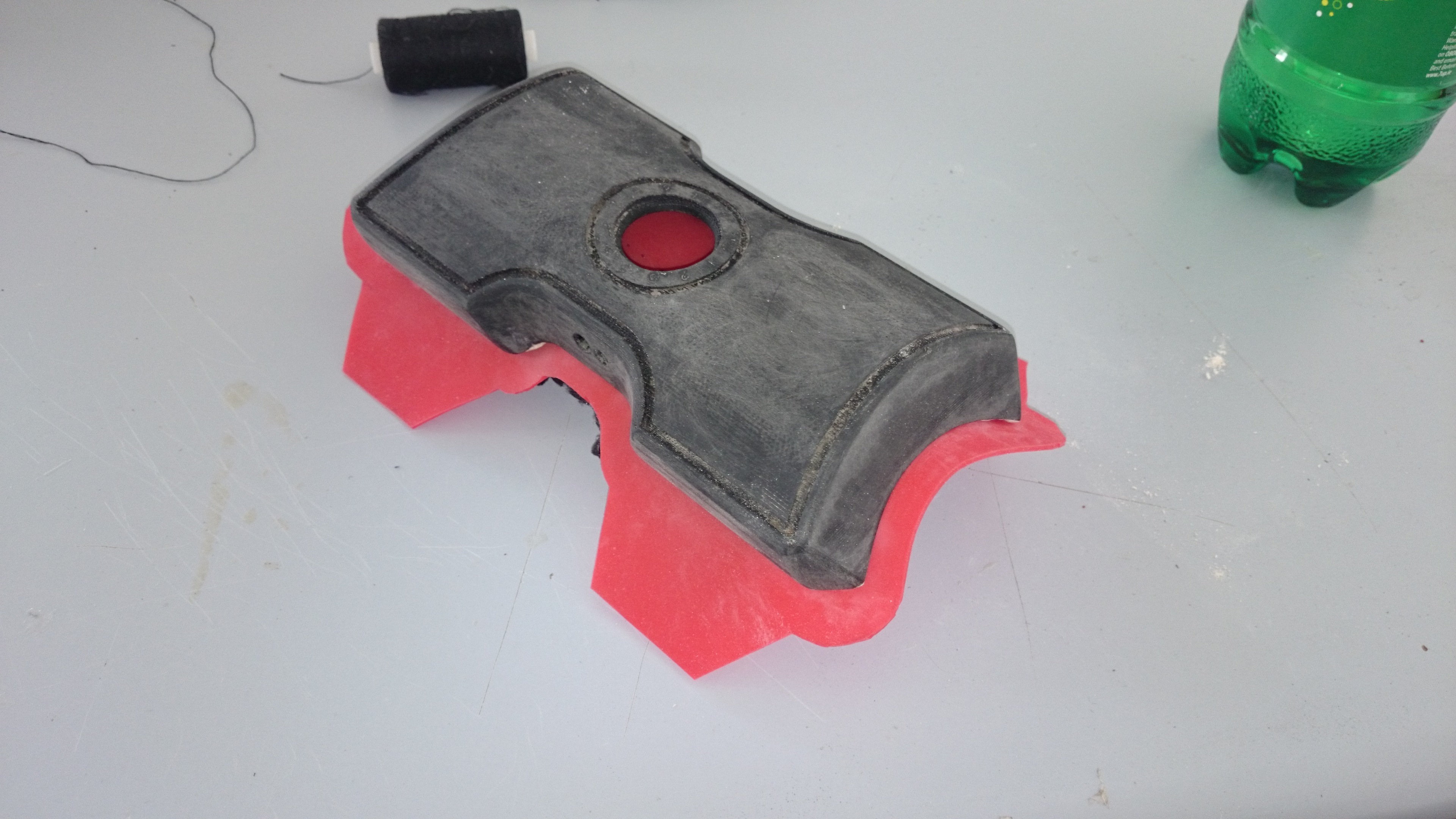
The second attempt on the rubber fit perfectly, we intended to have it glued permanently to the shell during assembly, it is here the rubber started giving us difficulties…..we had various glues and epoxy resins so we decided to test which would work best, we used a small sample of the rubber, not a single type of glue stuck to it, we picked up the rubber for €2, we hadn’t expected it to be literally non-stick to everything past typical foods. We had designed the shell with small pads to the inside to use as points of contact for adhesives. With the rubber failing to stick to anything we had to redesign the shell to use screws.
Modifying the Shell
We had one week left to finish the prototype so we couldn’t get a new version of the shell 3d printed in time so we decided to build up on what we had, we used epoxy to extend the platforms inside the shell so we could use them for screws.
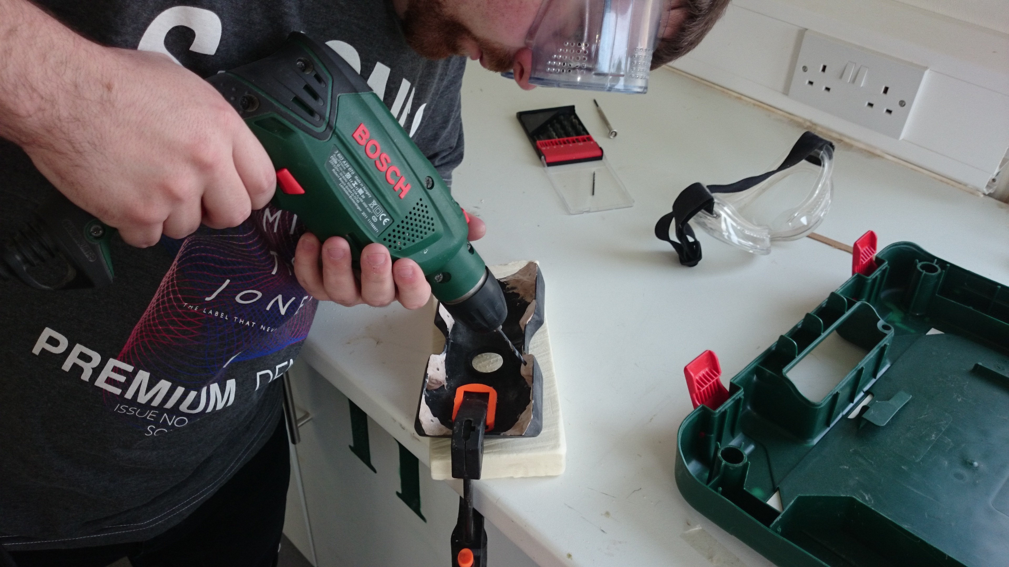
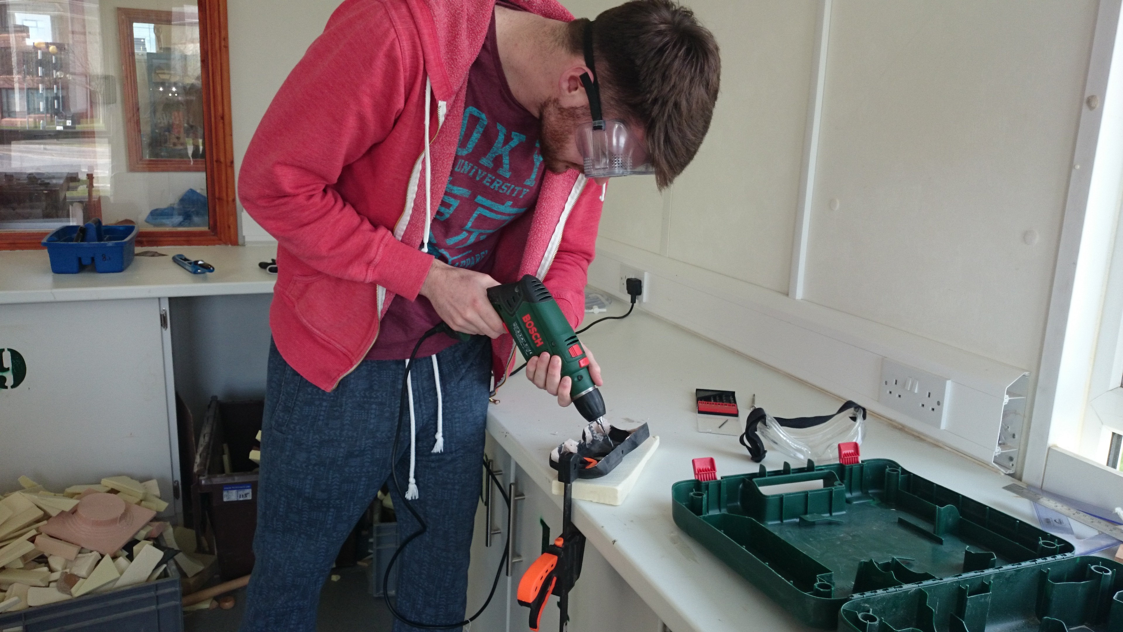
We used multiple drill bits to get the hole size right, we didn’t want to use the largest bit first for fear of damaging the shell so close to the deadline. Sadly the use of the epoxy made the inside of the prototype look scrappy and unappealing but given that the focus was the outside of the design, we accepted it.
Sanding and Painting
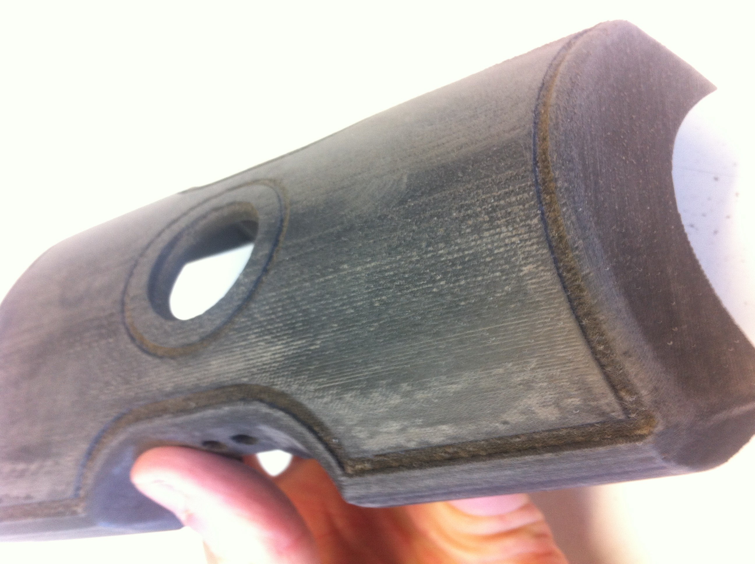
We learned from past projects and past mistakes with 3D printed parts on what to do in order to get an ideal finish. We started with sanding. Tomas dedicated an extensive amount of time to this part personally, going through various stages of dry sanding, cleaning, then wet sanding, then polishing, then repeating the process numerous times over until satisfied with the end result.
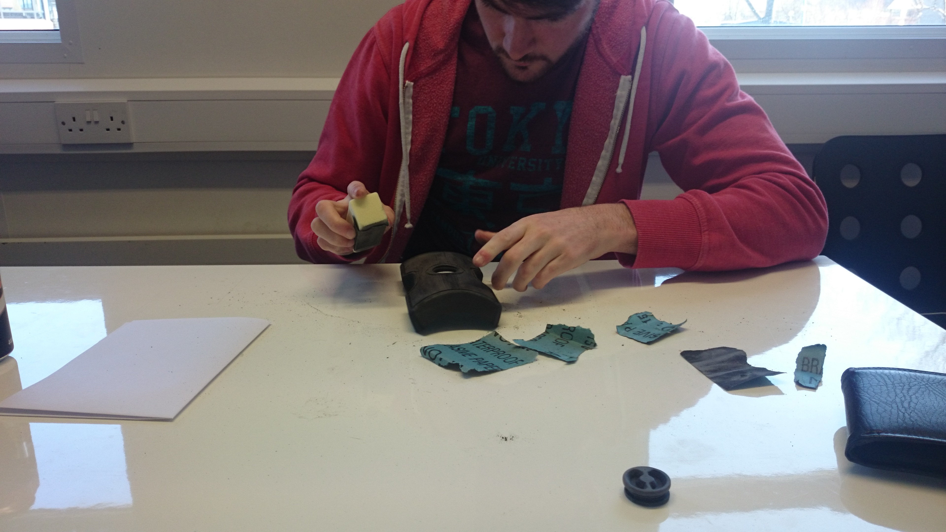
The main focus was the outside of the shell, any part that was visible, was carefully sanded and polished smooth.
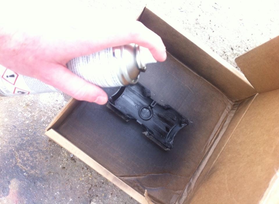
We found ourselves very lucky when it got around to painting the shell and dial pieces, the day was very warm and the weather resulted in each coat of paint being dry within 15 minutes if not 10. We gave the pieces thin coats and built up layers to avoid any paint dripping and to keep an even coat. We didn’t have proper masks so we did the painting out in the open and took turns spraying to avoid too much exposure to fumes. In the end we gave every piece 9 coats of paint.
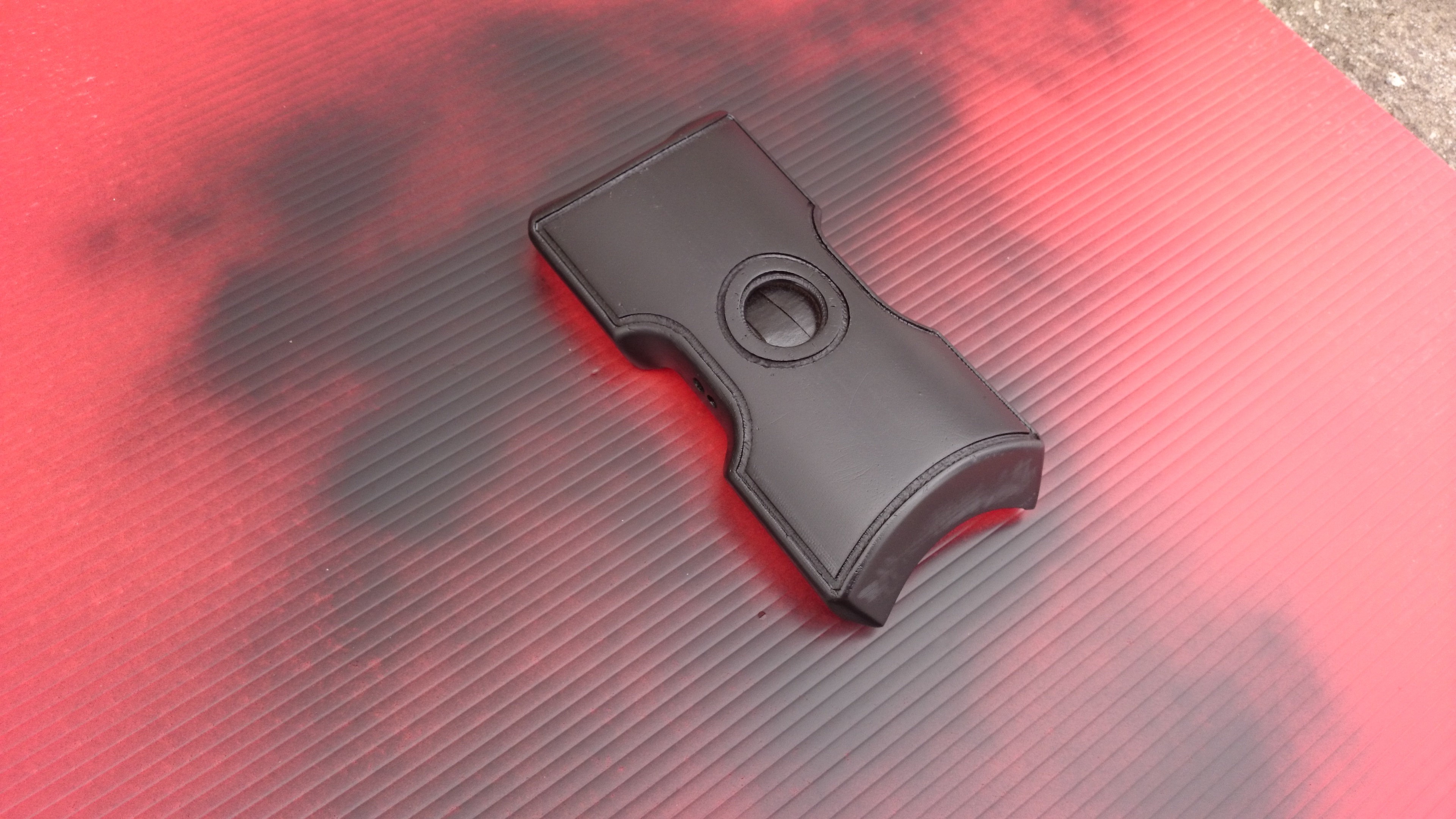
With the rubber being red and the elastic we intended to use having red lines running through it, we painted the design on the shell red, we intended to have coloured numbers on the shell but sadly the 3d printing only engraved these very faintly and they were lost entirely after sanding.
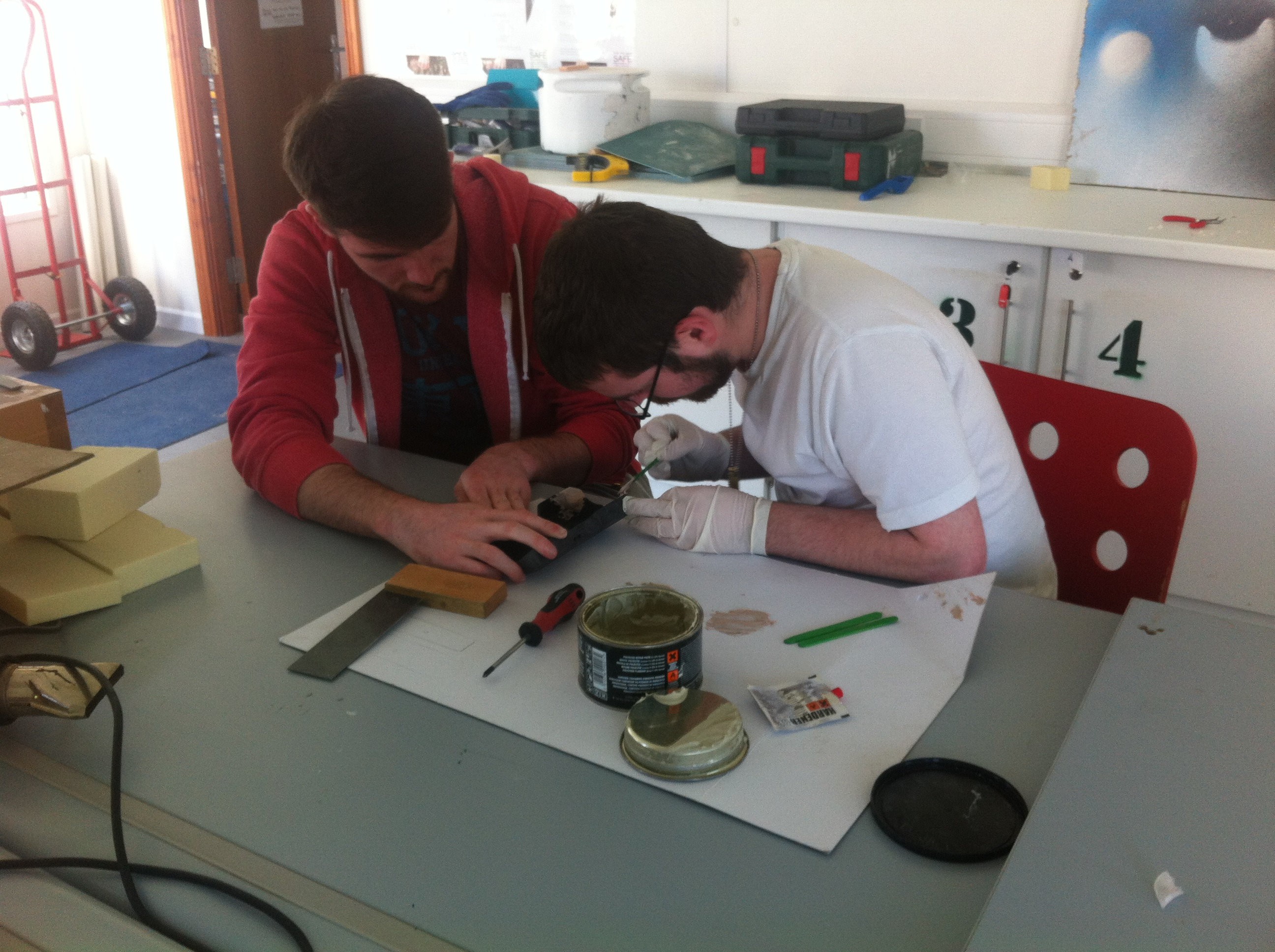
The engraved design was filled in using red enamel paint, this was done using a sharp tipped brush (tissue twisted to a point). The technique was to dip the tip in the paint and let it drip and fill the engraving, the tissue brush was replaced every so often to keep the tip pointed, the engravings were filled up with multiple layers and any air bubbles popped and filled in. A sharp Stanley knife and wet cloth was used at the end to neaten the edge as best as possible without damaging the black coat of paint.
Electronics
With very limited time left we had to scrap the idea of a working prototype, but we still wanted to incorporate some working electronics, even if only basic, we decided to have the lights work and a fake charging port that when a plug was inserted, it would turn on a red LED.
We had two options for the lights, scrap LED’s we pulled from old toys or use some mini round bulbs we pulled from an old set of Christmas lights, we wanted to exaggerate the lighting on the prototype and have it bright, so we initially went with the Christmas lights, though they were all white.
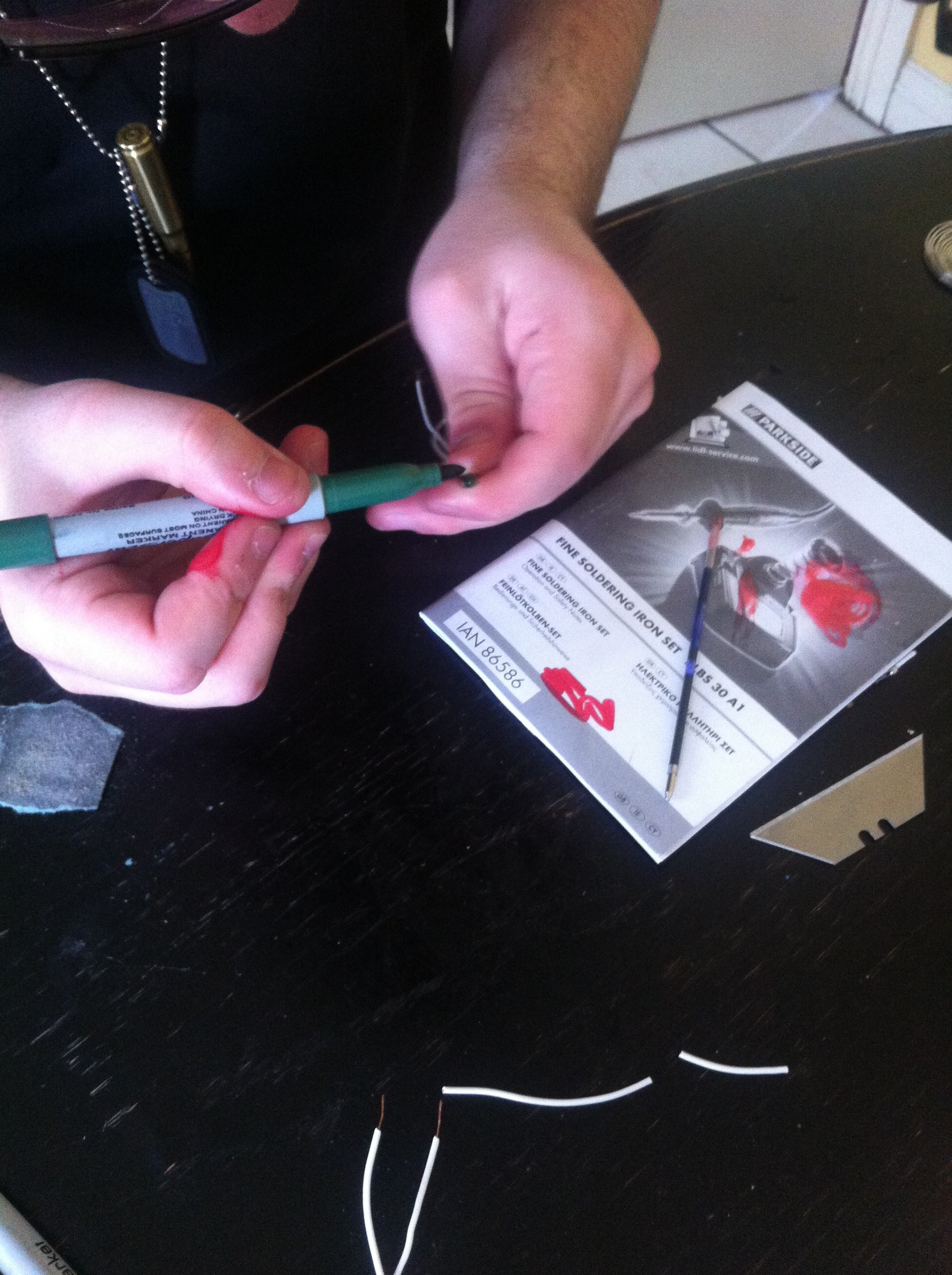
We tried recoloring the shell using sharpie marker in hopes of changing the lights colour, sadly this failed.
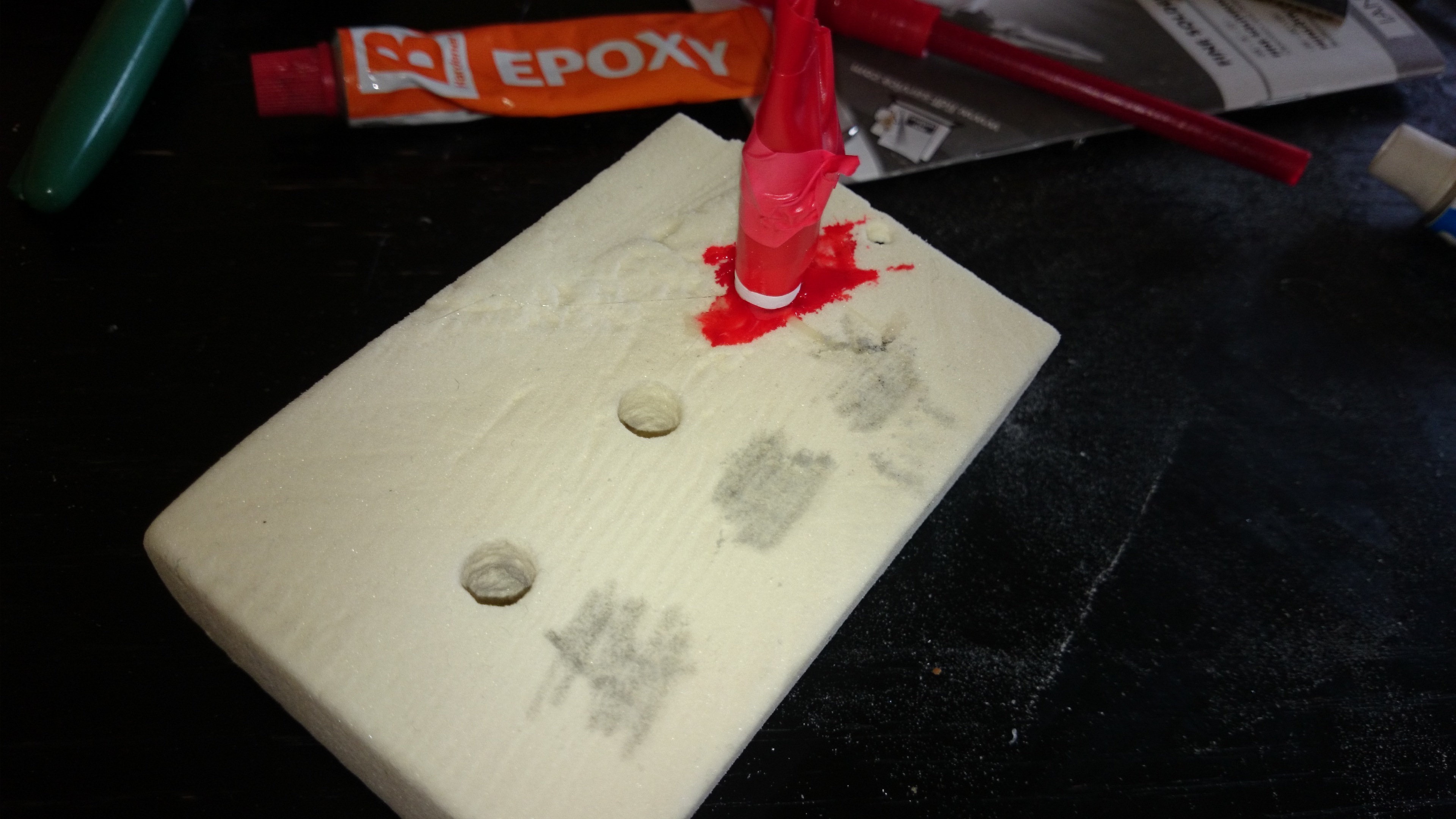
We had some clear epoxy laying around and some foam, so we
tried a crazy idea of making a new coloured shell over the lights, we cut round
10mm holes into the foam to match 10mm bulbs/LEDs, we then filled the holes
with clear epoxy resin and thin pulled the filters from the sharpie markers and
dripped the ink into the resin to dye it. We let the resin become tacky before
we pushed the bulbs into it, we used tape and paper rapped around the bulb to
prevent it falling over while it all dried.
We had some clear epoxy laying around and some foam, so we tried a crazy idea of making a new coloured shell over the lights, we cut round 10mm holes into the foam to match 10mm bulbs/LEDs, we then filled the holes with clear epoxy resin and thin pulled the filters from the sharpie markers and dripped the ink into the resin to dye it. We let the resin become tacky before we pushed the bulbs into it, we used tape and paper rapped around the bulb to prevent it falling over while it all dried.
We had success sort of, our hopes were raised when we tested the red light, it glowed so well, then they yellow and green glowed red as well, as to how we don’t know. We gave up on the bulbs after this failure and decided to use the LEDs.
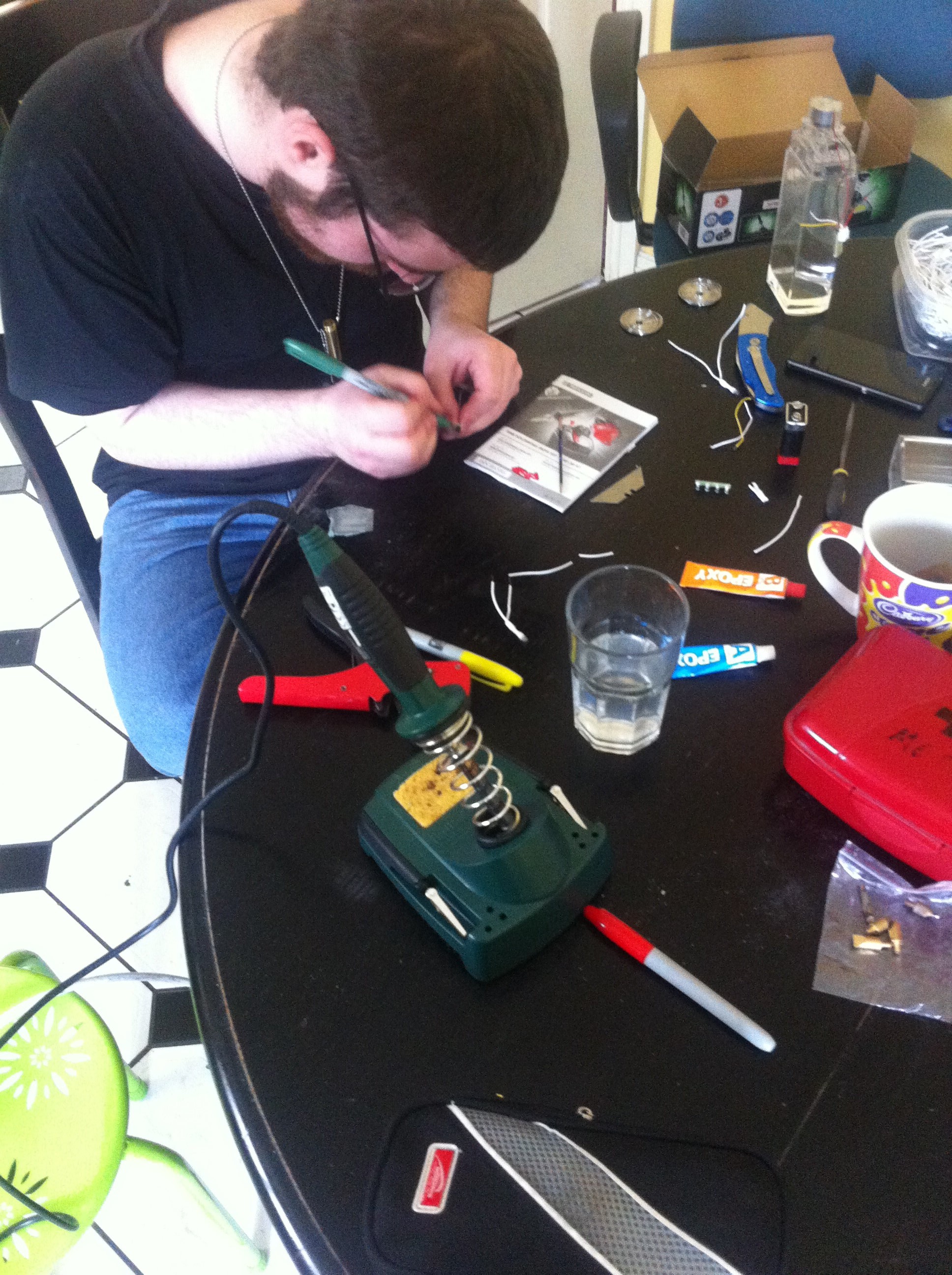
While the soldering above is pretty terrible, this was only a test circuit we made to make sure all LED’s worked, we had 1 RED burn about which luckily we had a replacement for (no replacements for yellow or green), each LED was given its own resistor out of paranoia of burning them out, even though 1 resistor should technically run fine.
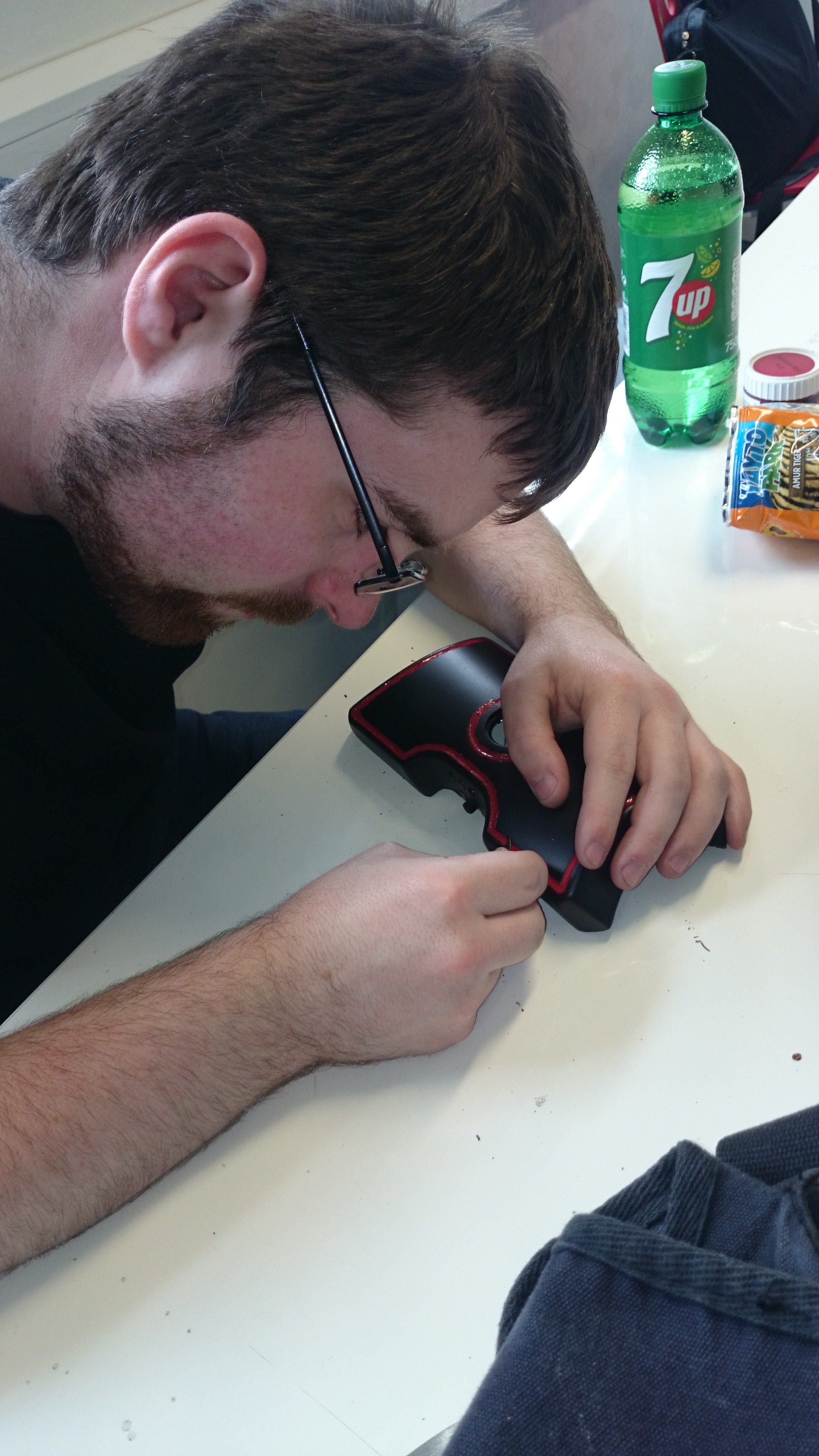
When the circuit proved to work, it was neatened up and put into the shell, we later had the leg of the yellow LED break the day before it was due. Thankfully pressure and lots of hot glue seemed to fix it. The circuit has two switches, independent of each other, the large switch turns on the main 3 LEDs while the second switch is a micro switch that when pushed turns on the charging LED. Note that no charging actually occurs. We had a nice surprise though with the charging LED, after we left the plug in for more than 3 seconds, it suddenly turned green on its own, we experimented around and found that it cycles between red and green every 3 seconds and always starts with red.
Padding and Elastic
We bought a woman’s top to use the fabric as material for padding, we cut it to match the shape of the rubber, since nothing could stick to the rubber, we were screwing it to the shell, the padding would be stitched to the rubber to hold it in place.
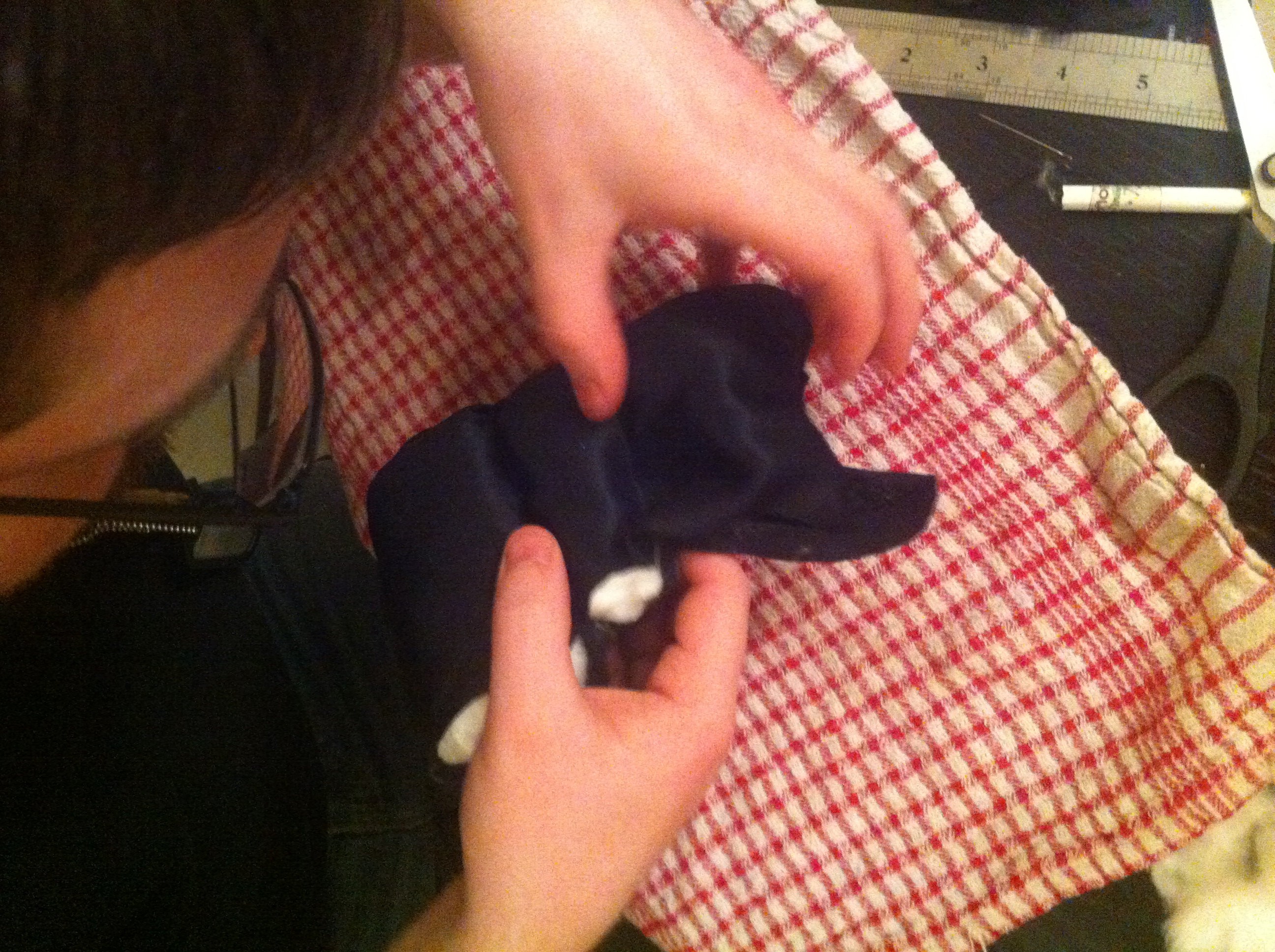
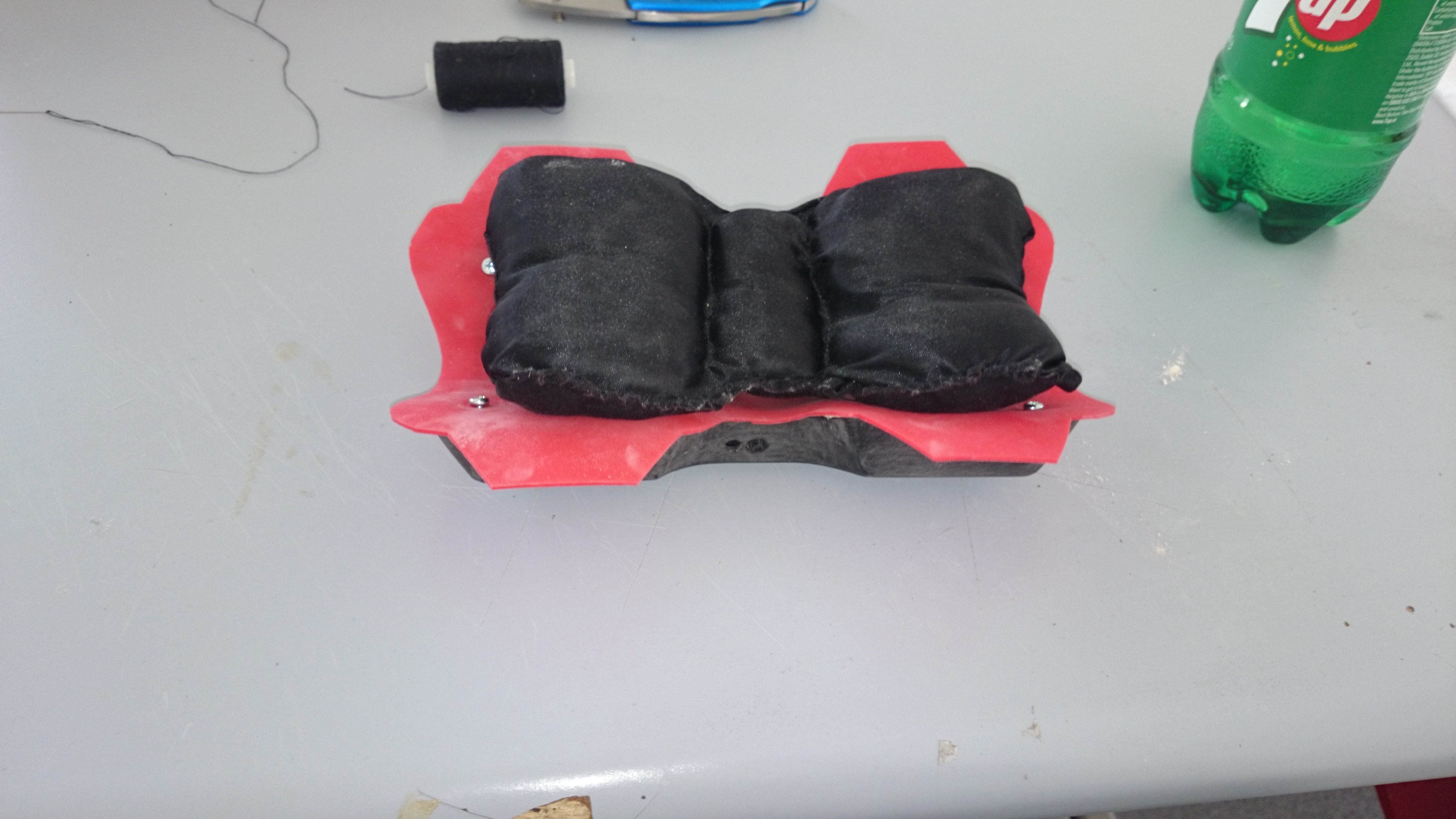
The padding was stitched together to form 3 cushioned segments, the padding wound up adding bulk to the overall design which our lecturer did not appreciate the look of, comparing the shape to a dicky bow. We removed this segment and went back to another material, a solid flat memory foam that was thinner.
The thinner foam proved just as comfortable while lowering the profile of the prototype.
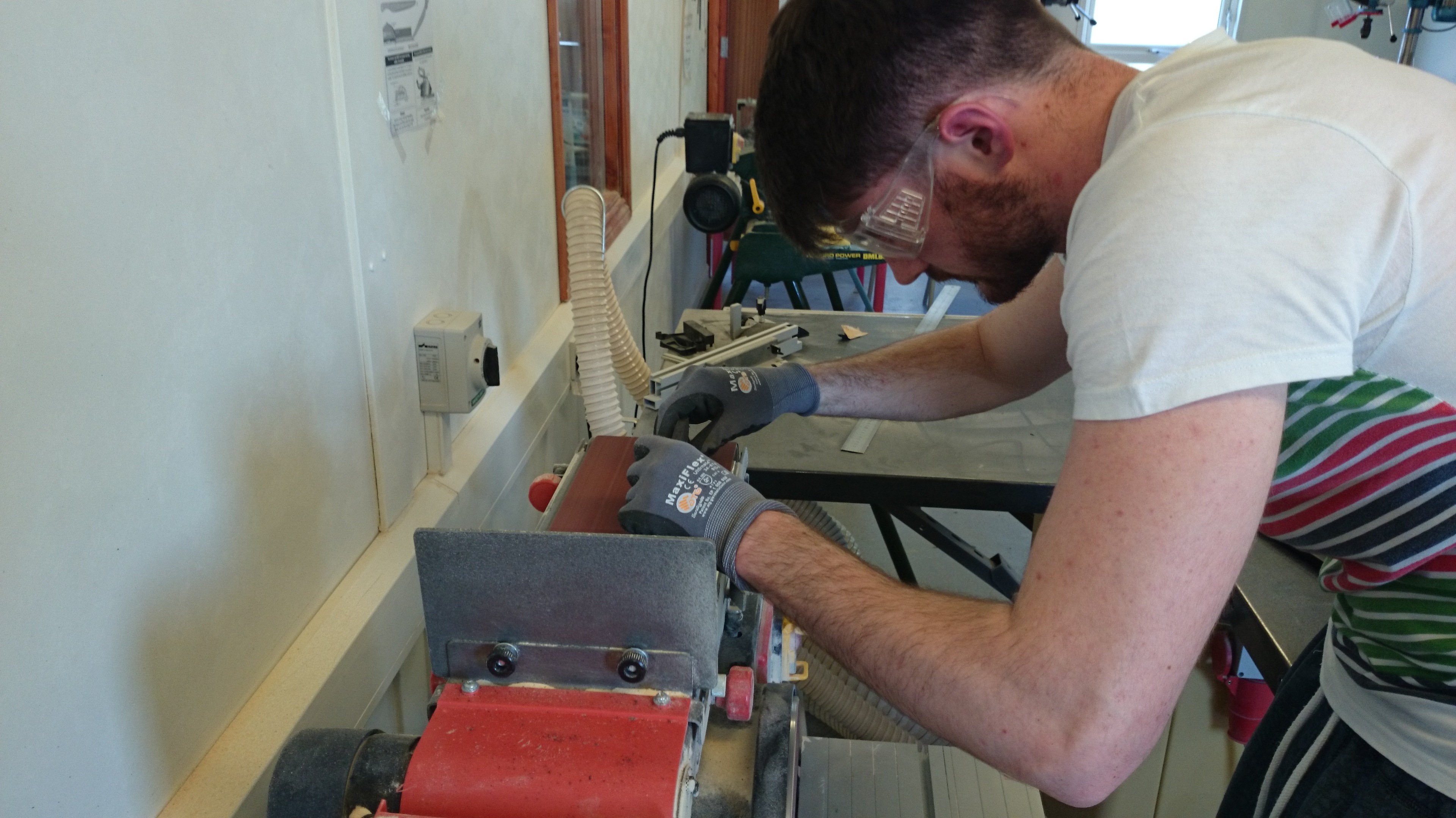
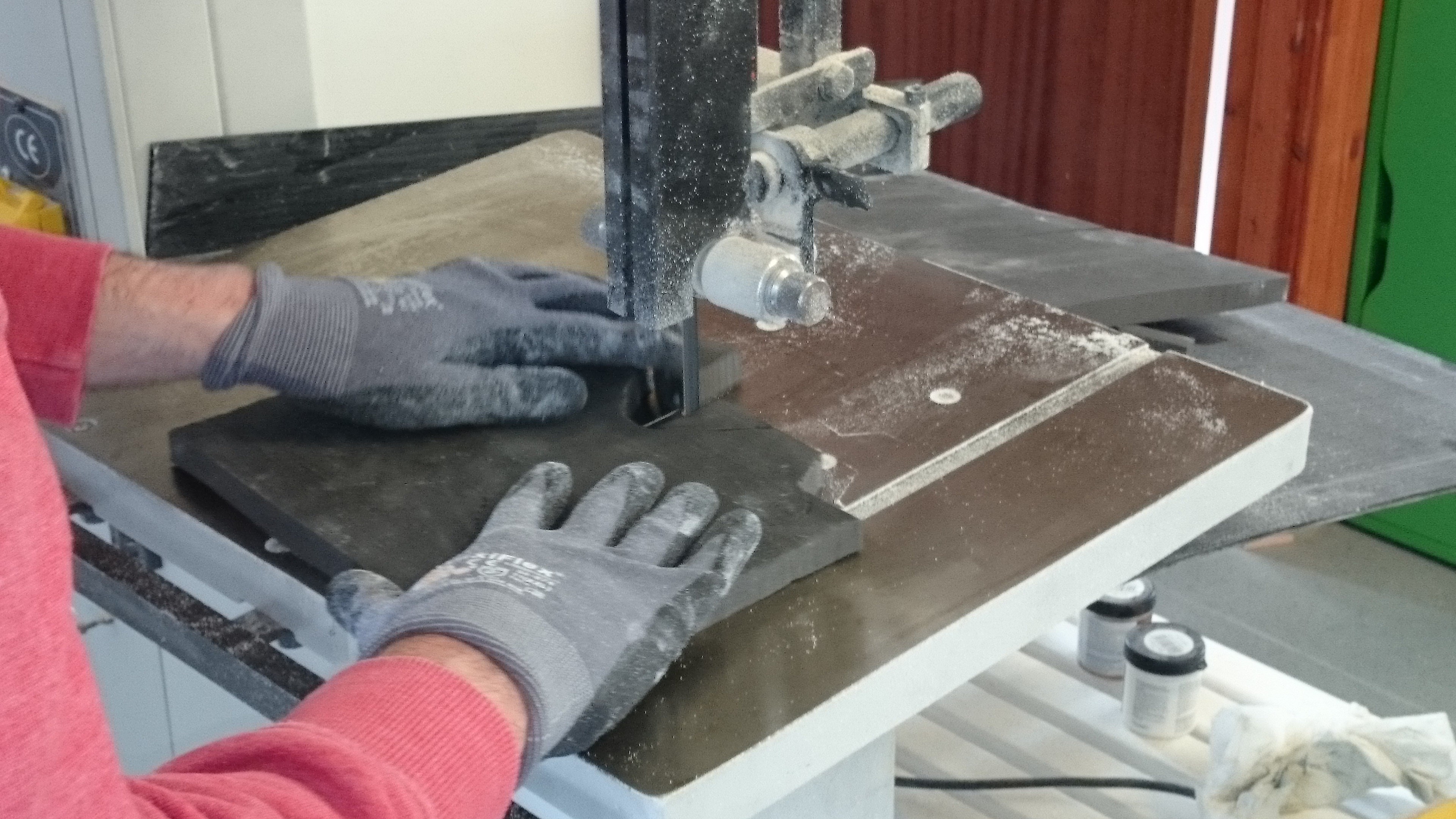
The edges were sanded down using a belt sander to get an even finish before being stitched to the rubber in place of the original padding.
We had two pairs of men’s boxers to get elastic from, one pair proved long enough to create the two sections of elastic we need. The elastic was cut from the boxers and a Stanley knife carefully used to remove the threading holding the boxers fabric to the elastic. This proved time consuming and required a delicate had so as not to cut the elastic and cause it to unravel.
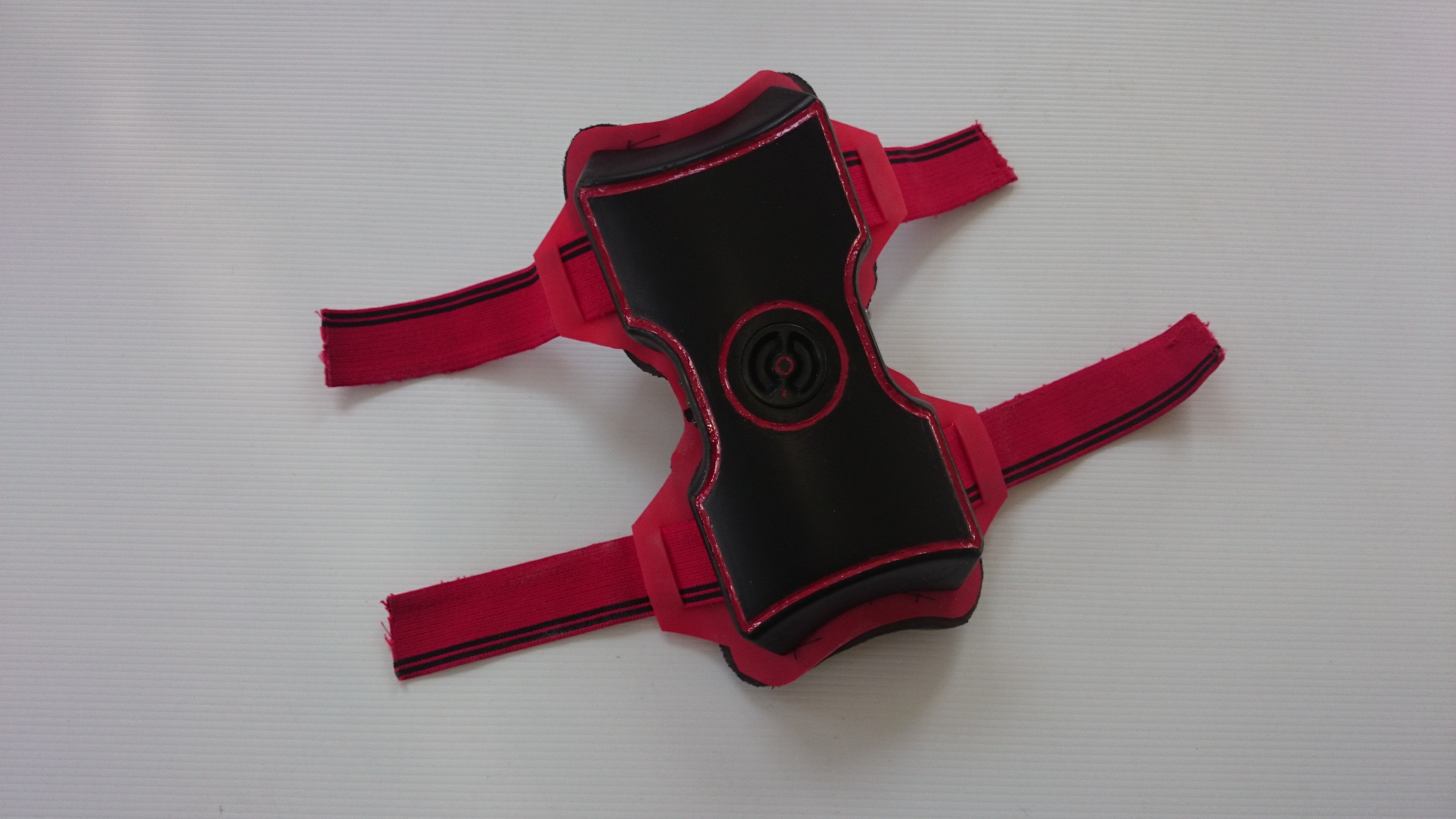
The end result can be seen above. The padding is stitched to the rubber, which has four slots cut through to allow the elastic to feed through. The padding and rubber is then screwed to the shell only due to the rubber we had rejecting all forms of adhesives. A heating element would be positioned within the shell on one side while the battery pack would be positioned on the other. Insulation used to protect the battery and the padding would work to disperse the heat throughout the area. Currently this isn’t possible given the batteries available today so this remains just a concept for a college project.
Discussions
Become a Hackaday.io Member
Create an account to leave a comment. Already have an account? Log In.