Close
0%
0%

SOLAR POWERED ARDUINO WEATHER STATION

A solar powered Arduino Weather Station to help the farmers

Similar projects worth following
In country like India, most of the people are dependent on agriculture.For effective planning in agriculture weather forecast is of utmost importance.So farmers are always interested in the Weather Forecasts.As farmers stay in remote areas, they have to wait for the news updates in TV, Radio or News Papers.Unfortunately this weather information is not the accurate data of their local environment rather it gives data of nearest weather forecasting station.
Being a son of a farmer, I decided to make a weather station to monitor the local weather and inform my father earlier.So that he can take early decision for his farm.
The weather station is consists of one transmitter and a receiver module.The transmitter module contain all the sensors and a RF transmitter.It is powered from a Solar panel.
The receiver module contain RF receiver and LCD display.The main processing units are two Arduino Boards.

The weather stations typically consist of two major parts:

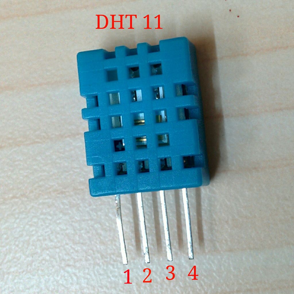
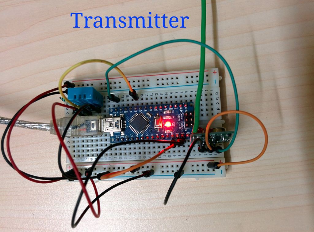
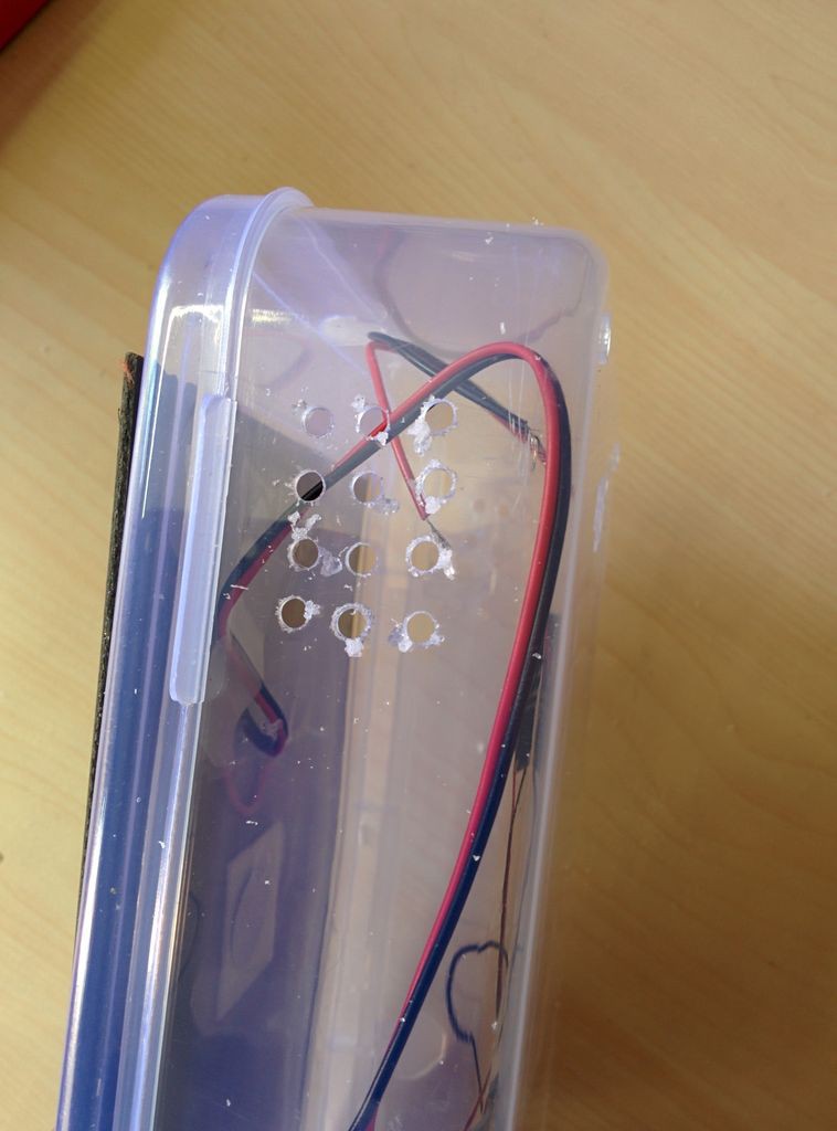
1. The sensors that sit outside and measure temperature,humidity, rainfall, and barometric pressure.This data is send wirelessly through a RF transmitter module to the display unit.I named the entire module as Transmitter module.(Tx).


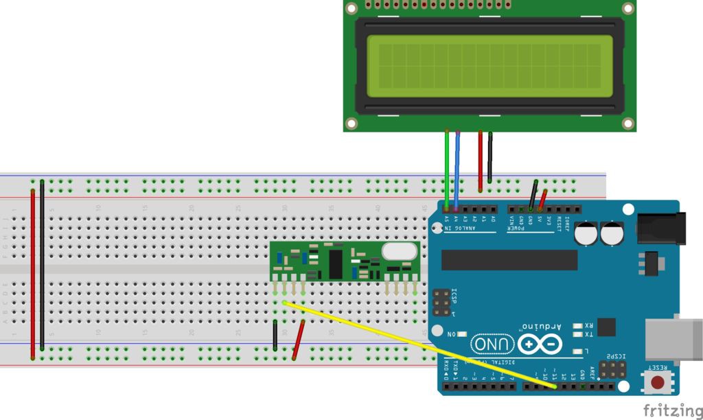
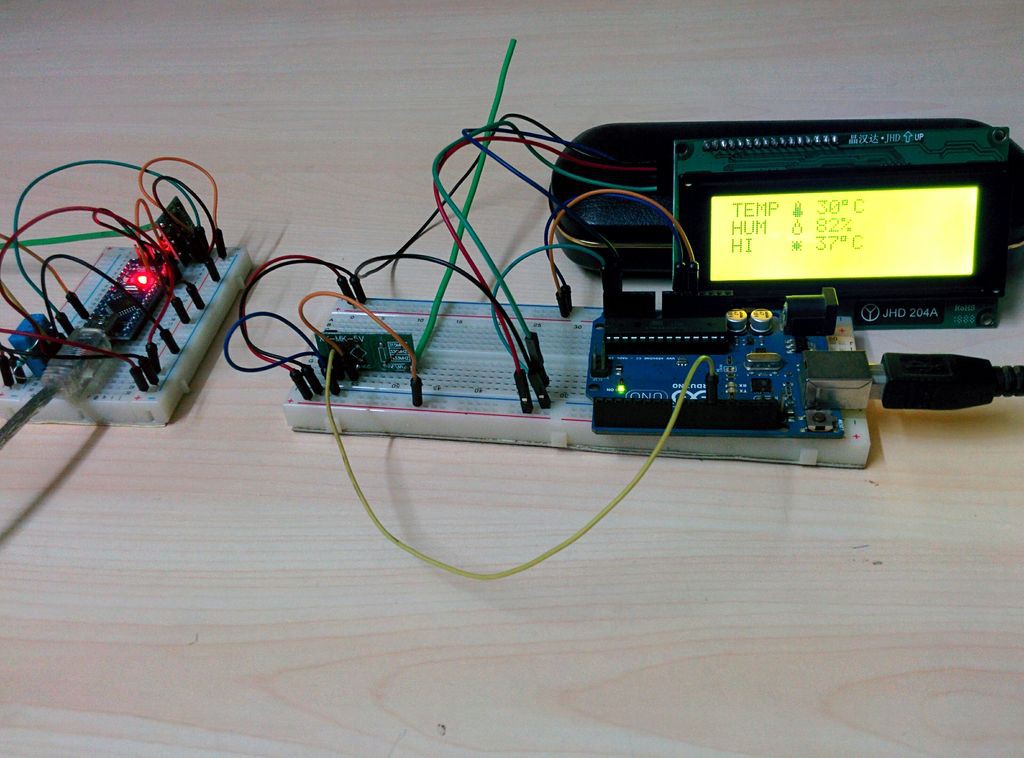
2. The display unit that lives inside in a convenient place so any one can read the external temperature,humidity etc. It equipped with a RF receiver to receive data from transmitter module.I named it as Receiver module (Rx).

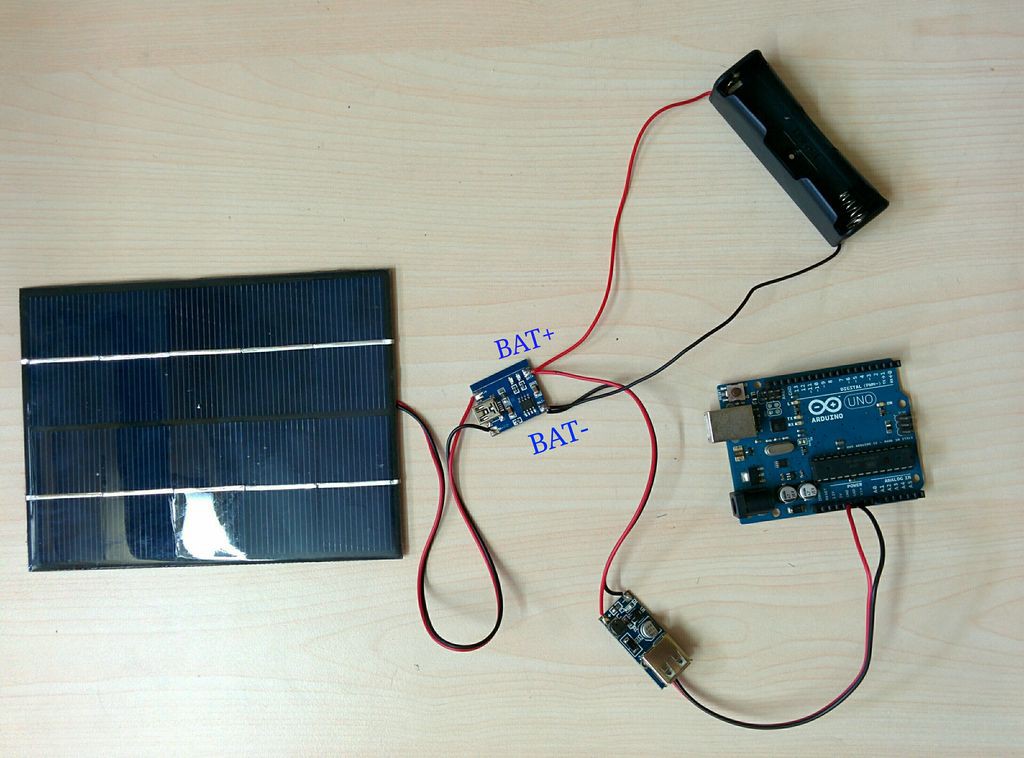
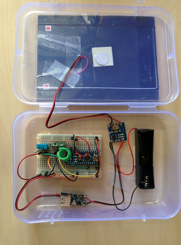
Both the module are run by the arduino micro controllers.

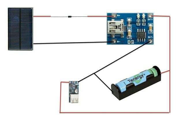
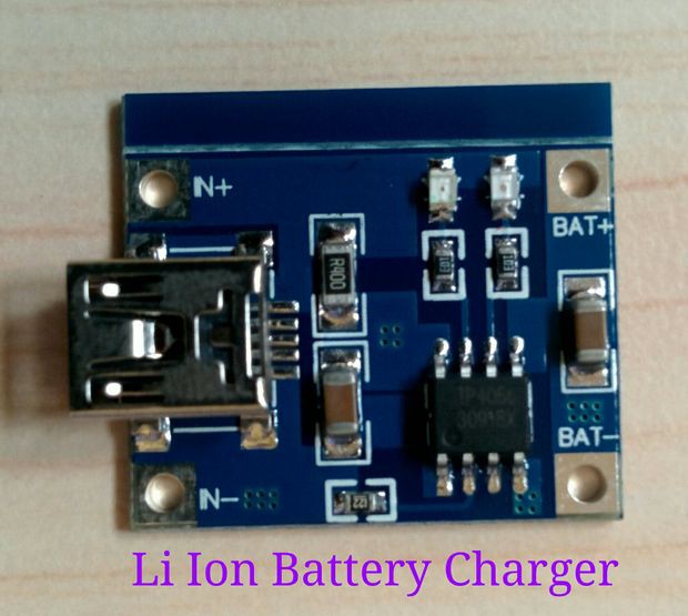
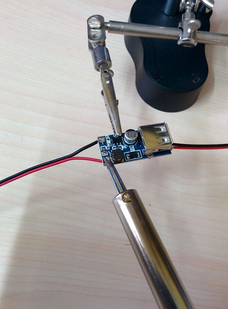
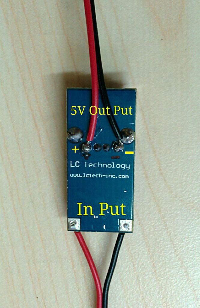
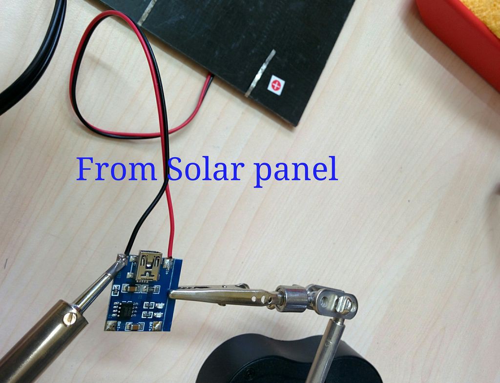
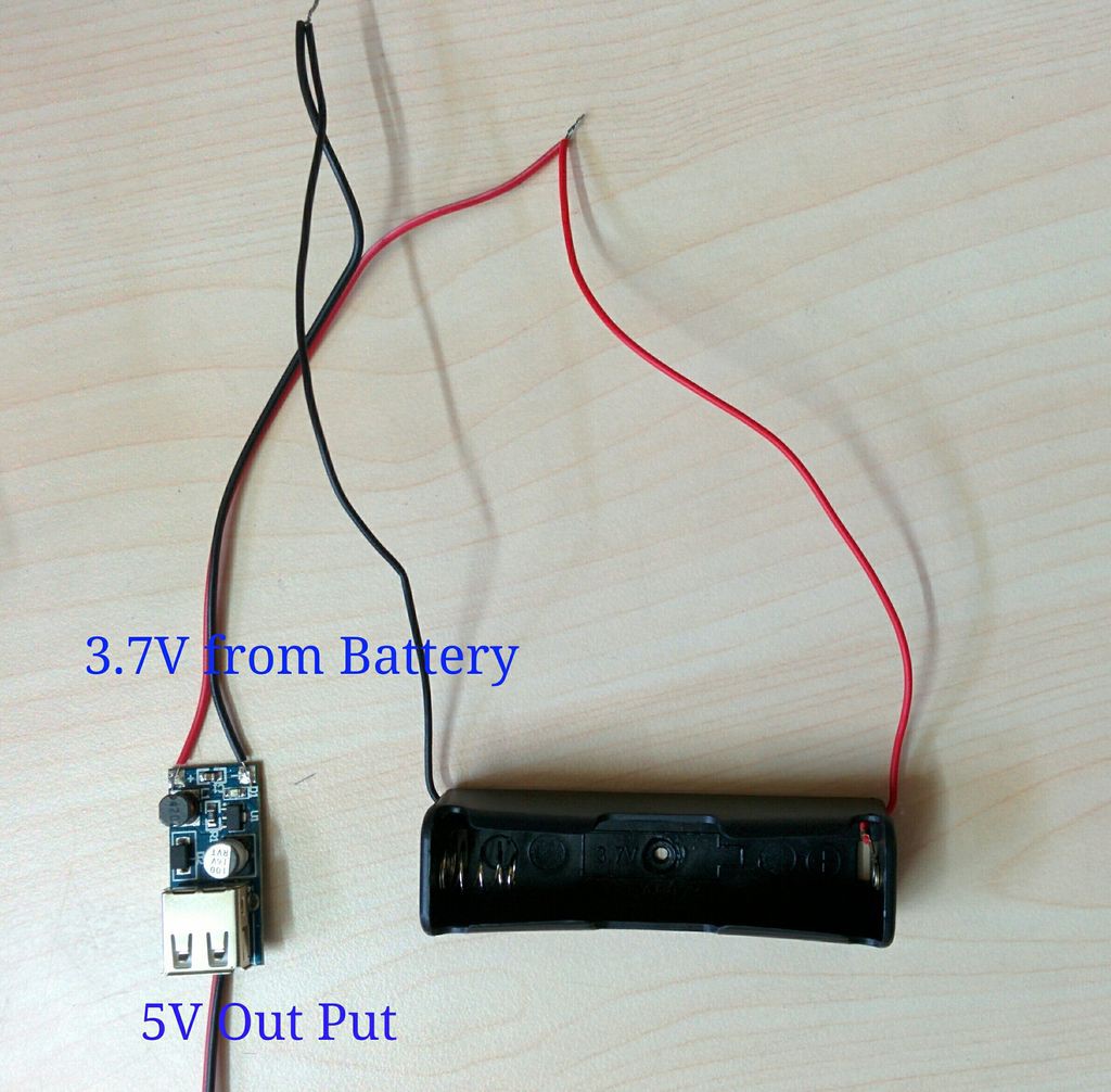
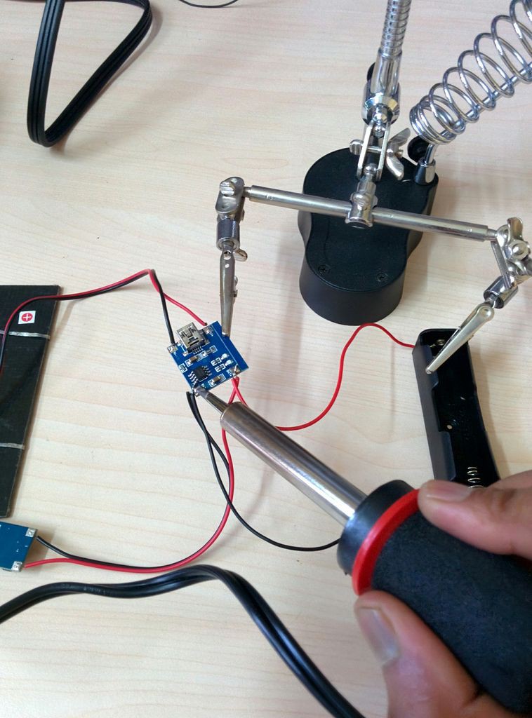
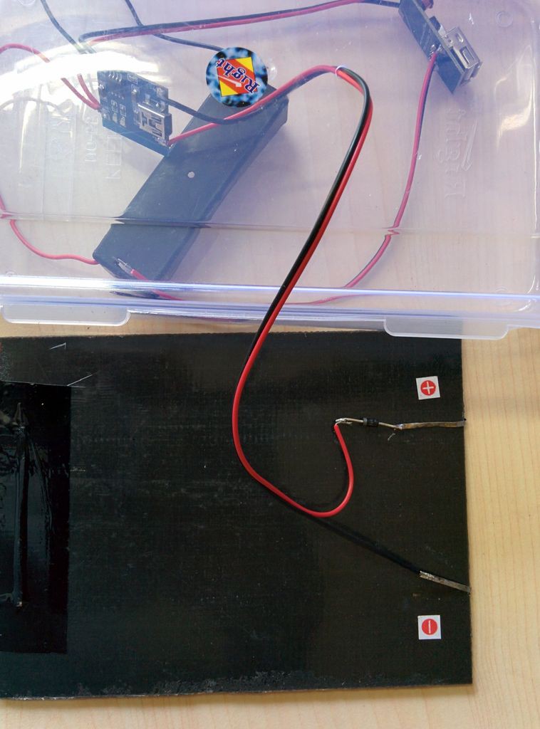
As the transmitter module is deployed in the field,we have to deal with the power management.It is impractical to run a long cable to provide power to the sensor’s location.This leaves relatively few practical options.

1. Connecting directly an Arduino board to a battery. Though it sounds good and obviously it would work, but your battery would be depleted in a matter of days because some components like voltage regulators,power led and USB interfacing chip in the arduino board are always drawing power.
But now a days high capacity battery packs are readily available in the market.Solar panels are getting more efficient and cheaper. Adding a boost converter in the circuits extract every last drops of juice out of battery.

2. Putting the arduino to “sleep mode" to consume even less power.

View all 16 components

  • Battery Life Estimation by Implementing Sleep Mode

    Open Green Energy06/28/2015 at 14:19 0 comments

    Picture of Battery Life Estimation

    temp_977081451.jpg

    temp_-509662963.jpg

    The battery life can be calculated by determining the average current for the circuit.

    Use the following general equation to calculate average current.


    Iavg = (Ton*Ion + Tsleep*Isleep ) / (Ton +Tsleep)

    Ton (arduino is active ) = 250 ms =0.25s and Ion = 16mA

    Tsleep = 5min =300s and Isleep = 200 uA (approx)

    It is very difficult measure the current during the sleep period .Some time I got zero reading.

    Iavg = 0.205 mA

    Operating Voltage =5 V

    Pavg=VxIavg =5x.205=1.026 mW

    Li Ion battery capacity =3000 mAh

    Battery voltage =3.7V

    Power =3.7x3000=11100 mWh

    Battery life = 11100/1.026 =10,818.7 hours = 15 months approximately

    From the above calculation it is clear that theoretically by using a fully charged 3000 mAh Li Ion battery we can run the arduino for 15 months.In practical due to battery self discharge this figure may be different.

    As the system is equipped with solar charging system ,we can run for few years without any interruption.

  • Alternatives for Power saving

    Open Green Energy06/28/2015 at 14:15 0 comments

    Picture of Alternatives for Power saving

    temp_-190727262.jpg

    temp_2089443491.jpg

    temp_44538794.jpg

    temp_1902883833.jpg

    IMG_20140909_153434.jpg

    temp_-2059572975.jpg

    >> The simplest method to reduce the power consumption is by passing the voltage regulator in the Arduino board.

    Buy a separate boost regulator circuit and connect its output to the 5 volt pin on the Arduino board, which bypasses the 5 volt regulator on board.This procedure is used in our project.

    >> using a "bare bones" board instead of arduino board.
    >> Disable the unnecessary led
    >> If you do not need time accuracy, then use the Atmega 328 internal 8MHz crystal instead of a external 16Mhz crystal.

    >> Operate Atmega 328 at 3.3V instead of 5V

    >>Turn off sensor as soon as possible

    To know more details on arduino power saving techniques click here


    The maximum power saving is done by using a Bare bones board.By using a bare bone board the power consumption can be reduced to micro amps level during sleep period.You can see the above figure.

    You can easily make this on a bread board by following the links bellow :

    1.Arduino on a Breadboard

    2.Arduino to a Microcontroller on a Breadboard
    Make bare bone pcb board by following the links bellow :

    Single Sided Really Bare Bones Board Arduino in EAGLE
    I will highly recommend for the bare bone board for any battery driven projects ( like sensors).

  • POWER OPTIMIZATION BY USING SLEEP MODE

    Open Green Energy06/28/2015 at 14:12 0 comments

    Picture of POWER OPTIMIZATION BY USING SLEEP MODE

    temp_-758114554.jpg

    temp_185183326.jpg

    temp_1442858346.jpg

    temp_-595250227.jpg

    The weather data does not change frequently.So we can take reading at an interval of 5mins.As we are taking readings at regular intervals, it is a fantastic way to save lots of power. A system with appropriate sleep schedules can run for several months on just two AA batteries.We are so lucky that Arduino has several sleep modes that can be used to reduce power consumption.

    This is most useful for any sensor networks.You can use this tricks in any of your stand alone sensor project.

    After searching through the internet for using the sleep modes, I found a simple but powerful library by Rocket Scream has a Lightweight Low Power library supports all AVR power down modes. Each mode has an associated library method that lets you control sleep duration using the watchdog timer.For a novice programmer like me it is very simple and easy to use.

    How to use LowPower Library :

    1. Download the library from GitHub
    2.Extract the zip file to the arduino library in your computer.
    3.Import the library in your code.
    4.Write the following one line code for power saving.
    "LowPower.powerDown(SLEEP_1S, ADC_OFF, BOD_OFF) ; "

    You can also pass different arguments to shut off individual peripherals. For different argument and sleep time refer the table provided by Lightweight Low Power Arduino Library.


    example code :

    #include "LowPower.h"
    void setup()
    { 
    // No setup is required for this library 
    } 
    void loop() 
    { 
    // Sleep for 8 s with ADC module and BOD module off 
    LowPower.powerDown(SLEEP_8S, ADC_OFF, BOD_OFF); 
    // Do something here 
    // Example: read sensor, log data, transmit data 
    }


    Lets use it in the blink code of arduino IDE example


    Apply "LowPower library" in Blink code

    #include "LowPower.h" // import the lowpoer library
    int led = 13; 
    void setup()
    { 
    pinMode(led, OUTPUT); 
    }
    void loop() 
    { 
    digitalWrite(led, HIGH); 
    LowPower.powerDown(SLEEP_1S, ADC_OFF, BOD_OFF); // instead of delay(1000) ; 
    digitalWrite(led, LOW); 
    LowPower.powerDown(SLEEP_1S, ADC_OFF, BOD_OFF); // instead of delay(1000) ; 
    }

    Before using the Lowpower library current taken by arduino

    51.7mA when led is ON

    47mA when led is OFF

    After using the Lowpower library current taken by arduino

    34.93mA when led is ON
    31.73mA when led is OFF

    Are you happy to reduce 32.43 % power ?? Hey there is still room to reduce the power consumption.
    Your arduino board have different power sucking components like power led,voltage regulator and USB interface chip which takes most of the power even when it is idle.

  • Li Ion Battery Pack for Powering the Arduino

    Open Green Energy06/27/2015 at 17:36 0 comments

    To power the Arduino I choose Li Ion battery (18650).If you look at the Periodic Table, you will find that Lithium is on the far left in the first column, where all the most reactive elements live.So during handling care should be taken.

    Caution :

    You must take certain precautions when dealing with Lithium Ion Batteries. In order to maintain a very precise voltage when charging. The 3.7V batteries we're using in this guide need to have a charging voltage of 4.2V.A volt high or a volt low can mean an out of control chemical reaction which can lead to danger.

    Don't worry a suitable Li Ion battery charge controller will solve the above problem.

    Circuit Connection :

    Solder the Input positive terminal of boost converter(red wire) and battery holder positive terminal(red wire) to the charging board's BAT + .

    Solder the Input negative terminal of boost converter(black wire) and battery holder negative terminal(black wire) to the charging board's BAT-.

    The boost converter output is a USB terminal. For powering a bread board circuit we need two wires for connection.So we have to modify something according our requirement.

    The usb have four terminals (5V,D-,D+and GND).

    Solder the red and black wire to the + and - respectively as shown in the back side of the boost converter.

    Note : The boost converter do not have any marking.So use my picture during soldering.

View all 4 project logs

  • 1
    Step 1

    1. Making The Transmitter :

    The transmitter module contain the various sensor for monitoring the weather.The DHT11 sensor is used for measuring temperature and humidity of the environment.It is good for 20-80% humidity readings with 5% accuracy and for 0-50°C temperature readings with ±2°C accuracy.

    I ordered the Barometric Pressure Sensor( BMP085) and rain fall sensor from eBay to forecast more weather data.For the time being I am happy with only temperature and humidity.

    The weather data is measured by DHT11 ,processed by a Arduino nano/bread board arduino and transmit it wirelessly through a RF transmitter.

    DHT11 Connection :

    DHT11 sensor have 4 pins :

    1->Vcc ,

    2->Data ,

    3->NC ,

    4 ->GND


    DHT11 -->ARDUINO

    Vcc-->5V
    Data-->D8
    NC --> No connection
    GND-->GND
    Connect a 10K resistor between VCC and Data pin of DHT11


    RF Transmitter Connection :

    The RF transmitter has 3 pins ( VCC,Data and GND).

    RF Transmitter -->ARDUINO

    VCC --> 5V
    Data-->D11
    GND-->GND

    Note : Add a antenna in the RF transmitter to increase the range.click here

    After connecting every thing, upload the Tx_code attached bellow

    /*.............................................................
    Sending Multiple Variables Using VirtualWire. Transmitter
    Author: Rodrigo Mompo Redoliww  http://controlrobotics.rodrigomompo.com
    Modified by  deba168 from INDIA on 05/09/2014
    ..............................................................*/
    #include <VirtualWire.h>
    #include "LowPower.h"
    #include "DHT.h"
    #define DHTPIN 8     // what pin we're connected to
    #define DHTTYPE DHT11   // DHT 11 
    DHT dht(DHTPIN, DHTTYPE);
    int ledPin = 13;
    char Msg[30];// The string that we are going to send trought rf transmitter 
     
    void setup() 
    {
      dht.begin();  // initialing the DHT sensor
      pinMode(ledPin,OUTPUT);
      // VirtualWire setup
      vw_setup(2000); // Bits per sec
      vw_set_tx_pin(12);// Set the Tx pin. Default is 12
    }
     
    void loop() 
    {
     
      // Read and store Sensor Data
      int humidity = dht.readHumidity();
      int temp = dht.readTemperature();
      int f = dht.readTemperature(true);
      int hi_f = dht.computeHeatIndex(f,humidity); //heat index in fahrenheit
      int heat_index  =(hi_f-32)*5/9; // convert heat index to celcius
      sprintf(Msg, "%d,%d,%d", humidity,temp ,heat_index);
     // Turn on a light to show transmitting
      digitalWrite(ledPin, HIGH); 
     //LowPower.powerDown(SLEEP_250MS, ADC_OFF, BOD_OFF);  
      delay(100); 
      vw_send((uint8_t *)Msg, strlen(Msg));
      vw_wait_tx(); // Wait until the whole message is gone
     // Turn off a light after transmission
      digitalWrite(ledPin, LOW); 
      // put 5 mins sleep mode
      // As lowpower library support maximam 8s ,we use for loop to take longer (5mins) sleep
      // 5x60=300
      //300/4=75
      for(int i=0;i<75;i++)
      {
      LowPower.powerDown(SLEEP_4S, ADC_OFF, BOD_OFF);    // Instead of delay(4000); 
     //delay(4000);
      }
    }
  • 2
    Step 2

    2. Making the Receiver :


    The receiver module receive the weather data by a RF receiver and it is processed by Arduino UNO .The processed data is displayed through a 20x4 char LCD display.You can also choose a 16x2 LCD also.The main reason for using a 20x4 char LCD is display is that I can display large number of weather parameters.


    I add a I2C module to the LCD for reducing the number of connection with arduino (requires only 4 wires).

    If you don't have a I2C module go to my tutorial on LCD tutorial for connection and example code.

    LCD connection :

    The I2C LCD have only 4 pins (GND,VCC,SDA,SCL)

    LCD-->ARDUINO

    GND-->GND
    VCC-->5V
    SDA-->A4
    SCL-->A5

    RF receiver Connection:

    The RF receiver has 3 pins ( VCC,Data and GND).
    RF Receiver -->ARDUINO

    VCC --> 5V
    Data-->D11
    GND-->GND

    Note : Add a antenna in the RF receiver to increase the range.click here

    After connecting every thing upload the Rx_code attached bellow

    /*.............................................................
     Sending Multiple Variables Using VirtualWire. Receiver
     Author:Rodrigo Mompo Redoli http://controlrobotics.rodrigomompo.com
     modified by deba168 from INDIA on 06/09/2014
     ..............................................................*/
    
    #include <Wire.h> // use Wire library for protocol i2c (A4 = SDA & A5 = SCL)
    #include <LiquidCrystal_I2C.h> // use LiquidCrystal_I2C library for control LCD on i2c protocol
    #include <VirtualWire.h> // use Virtual library for decode signal from Rx module
    
    byte thermometer[8] = //icon for thermometer
    {
      B00100,
      B01010,
      B01010,
      B01110,
      B01110,
      B11111,
      B11111,
      B01110
    };
    
    byte droplet[8] = //icon for droplet
    {
      B00100,
      B00100,
      B01010,
      B01010,
      B10001,
      B10001,
      B10001,
      B01110,
    };
    byte hi[8]=    //icon for heat index
    {
      0B00000,
      0B00000,
      0B10101,
      0B01110,
      0B11111,
      0B01110,
      0B10101,
      0B00000,
    };                 //(addr, EN,RW,RS,D4,D5,D6,D7,BL,BLpol)
    LiquidCrystal_I2C lcd(0x27, 2, 1, 0, 4, 5, 6, 7, 3, POSITIVE); //change the address as per your I2C module
    // Sensors 
    int humidity=0;
    int temp=0;
    int heat_index=0;
    char MsgReceived[21]; 
    int led = 13; //pin for LED
    
    void setup() 
    {
      lcd.begin(20,4); // set up the LCD's number of columns and rows: 
      lcd.backlight(); //backlight is now ON
      pinMode(led, OUTPUT); 
    
      // VirtualWire 
      // Bits per sec
      vw_setup(2000);
      // set pin for connect receiver module 
      vw_set_rx_pin(11);  
      // Start the receiver PLL running
      vw_rx_start();       
    
      lcd.begin(20,4);   // initialize the lcd for 20 chars 4 lines, turn on backlight
      lcd.backlight(); // finish with backlight on  
      lcd.createChar(1, thermometer);
      lcd.createChar(2, droplet);
      lcd.createChar(3,hi);
      lcd.clear(); // clear the screen
    
    } // END void setup
    
    void loop()
    {
      uint8_t buf[VW_MAX_MESSAGE_LEN];
      uint8_t buflen = VW_MAX_MESSAGE_LEN;
      //Taking the data from the control base
      if (vw_get_message(buf, &buflen)) 
      {
        digitalWrite(led, HIGH);
        delay(100);
        int i;
        // Message with a good checksum received, dump it. 
        for (i = 0; i < buflen; i++)
        {            
          // Fill Msg Char array with corresponding 
          // chars from buffer.   
          MsgReceived[i] = char(buf[i]);
          //Serial.print(MsgReceived[i]);
        }
    
        sscanf(MsgReceived, "%d,%d,%d",&humidity, &temp,&heat_index); // Converts a string to an array
        digitalWrite(led, LOW); 
        lcd_display();
        memset( MsgReceived, 0, sizeof(MsgReceived));// This line is for reset the StringReceived
      }
    }
    void lcd_display()
    { lcd.setCursor(1,0);
      lcd.print(" WEATHER STATION ");
      lcd.setCursor(4,1);
      lcd.print("TEMP");
      lcd.setCursor(9, 1);
      lcd.write(1);
      lcd.setCursor(11, 1);
      lcd.print(temp);
      lcd.write(0b11011111);
      lcd.print("C");
      lcd.setCursor(4,2);
      lcd.print("HUM");
      lcd.setCursor(9, 2);
      lcd.write(2);
      lcd.setCursor(11, 2);
      lcd.print(humidity);
      lcd.print("%");
      lcd.setCursor(4,3);
      lcd.print("HI");
      lcd.setCursor(9, 3);
      lcd.write(3);
      lcd.setCursor(11, 3);
      lcd.print(heat_index);
      lcd.write(0b11011111);
      lcd.print("C");
    }


  • 3
    Step 3

    3. Making the Enclosure for Transmitter :

    I used a plastic box for transmitter module enclosure.

    Make a hole in the top side of the plastic box for inserting wire from the solar panel.

    Make small holes in the side wall (opposite face) for ingress of fresh air ( to measure the accurate data ).see the pics.

    Place the charging circuit (made earlier) inside the box.

    Take out the wires from li ion battery charger (IN+ and IN-)

    Solder the positive terminal of solar panel to the positive terminal of diode and negative terminal of the diode to the red wire from the the charger.

    Solder the black wire to the solar panel negative terminal.

    For mounting the solar panel and battery holder I used skotch mounting pad.The mini bread board have inbuilt pad to stick.

    Use tap to stick the wire firmly.

    Connect the 5V (+) and GND (-) terminals of boost converter to the bread board red rail(+) and blue rail (-) respectively.

    To test it expose to sunlight ,you will see red led in all (arduino,boost converter,charging) the boards will glow.

View all 4 instructions

Enjoy this project?

Share

Discussions

Ed wrote 07/22/2015 at 12:45 point

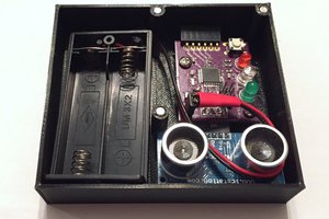
Very interesting project. yet as long as it is only a DHT11 and possibly a bmp180 or bmp085, an attiny85 will do the job as well, also on the receiving end. 
But yes, Arduino's cost next to nothing anymore :-)
Nevertheless, interesting project

  Are you sure? yes | no

Valent Turkovic wrote 07/22/2015 at 11:56 point

Suggestion for 3W solar panel (twice the power) for almost same price - http://www.buyincoins.com/item/38418.html

  Are you sure? yes | no

Andy from Workshopshed wrote 06/30/2015 at 15:45 point

Yes, that low power library is a nice wrapper for some obscure AVR code. I used that in my project too.

  Are you sure? yes | no

Similar Projects

Does this project spark your interest?

Become a member to follow this project and never miss any updates