Close
0%
0%

A Versatile Labtool

A cost effective, multi-pronged data acquisition tool to turn your computer into a workbench for science and electronics experiments.

Similar projects worth following
This USB powered Unit plugs into your computer and lets you study a wide range of phenomena.

The built in measurement capabilities include Scopes, Frequency Counters, Logic Analyzers, and configurable gain stages.

It also includes sine/triangle/square waveform generators, as well as several programmable voltage and current sources.

Add-on boards, both wired as well as wireless(NRF+MCU), enable measurement of physical parameters ranging from acceleration and angular velocity, to luminous intensity and Passive Infrared.

Calibrated against professional equipment to obtain good accuracy.

The Python library and associated experiment specific Apps(PyQt4) using a variety of powerful modules facilitate data analysis with interactive visuals.

WiFi option with ESP8266: ESP8266 used as a transparent WiFi/UART Bridge

Production version here : This project has been adapted for mass production, and has been packaged along with an SBC running the necessary software.
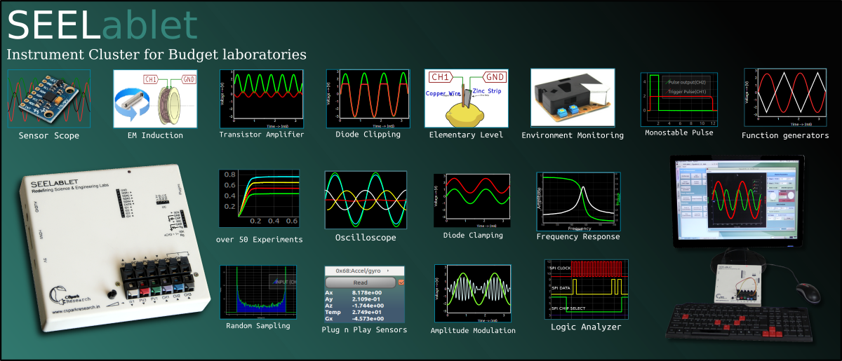
The software has over 70 different experiments, and includes a custom experiment designer.


What's this all about... And what is the problem you're trying to solve?

____Shortage of funds restrict teaching labs, and stifle creativity.

A ) Learning through experimentation offers a much clearer view of phenomena than merely trusting theory.

But, Setting up a well equipped teaching lab for science and electronics can turn out to be a very expensive affair.

Each student will require a minimum set of instruments comprising of multimeters, scopes, various sensors, and so on, in addition to the experiment specific hardware.

____Accuracy.

B ) These instruments must also be reasonably accurate for the results to tally with theoretical predictions such as the time constant of an oscillator, or the value of acceleration due to gravity.

____Usability

C) A common, program based interface to access all the instruments associated with a particular experiment allows much greater flexibility and control. A primary requirement for this is that the instruments must all use well documented control inputs interface-able with a computer. Unfortunately, documented control interfaces are rare in the low-end market.


What is the solution being attempted ( Or, What are your goals for this project )?

____Solve all the above, and balance cost with performance!

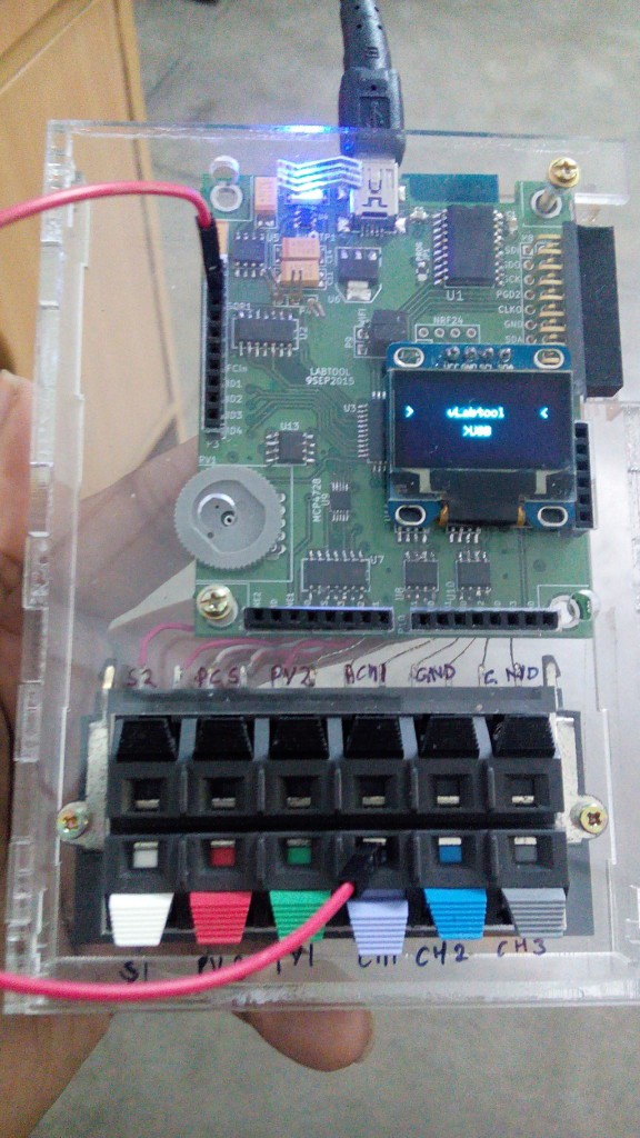
This project can be called a base board with an essential set of carefully calibrated instruments with design focused on being able to support a variety of limited audience, niche instruments ( Think high resolution ADCs, DACs, Signal modulators , and wireless modules ) . Significant room for improvement has been left in the form of an expansion slot. Here's an example add-on board for a 24-bit ADC used for calibration.


___How?

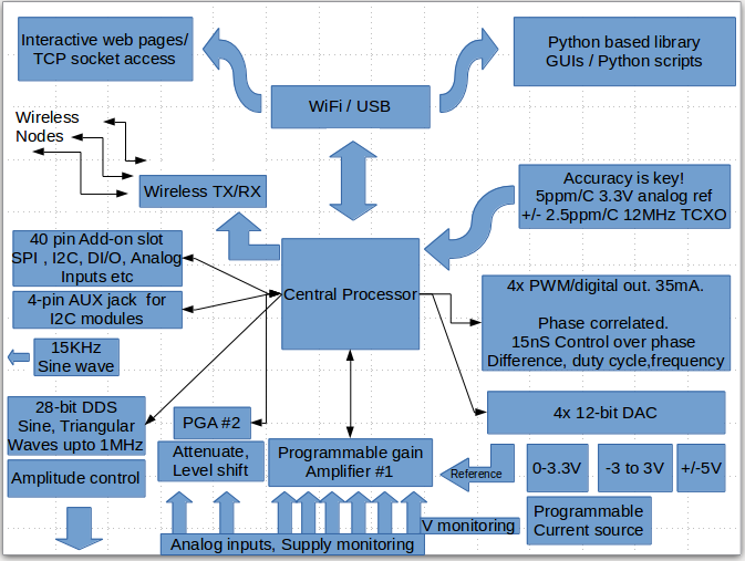
A processor with a fairly powerful set of peripherals is complemented with a variety of analog and digital tools. The setup connects to a computer via USB, and acts as a slave device that measures or controls as per instructions sent by the user via Python programs or graphical apps.
____Maintaining accuracy

An accurate, temperature compensated clock source is chosen as the reference for the digital instruments, and a low-drift voltage reference is chosen for maintaining the predictability of analog instruments. These two together ensure that readings stay consistent over a reasonable temperature range .
The device is then calibrated against professional instruments that rectify non-linear behaviour as well as offsets and slopes in order to squeeze out maximum performance.

___Choosing an interface

Python was chosen as the main interface language owing to the vast computational and visualization resources it has. These are essential for analysing acquired data and extracting physical parameters. It's also quite easy to learn, and since quite a few schools already teach it, we are but one step away from bridging the gap between software based learning, and experiment oriented methods.

*Additional interfaces: Standalone modes based on a plug-and-play display, as well as WiFi are part of the plan.

____What if you just can't write code, but are quite adept at designing experiments.

Several graphical interfaces with control and display widgets have already been designed. Check out the videos at the bottom of the page.
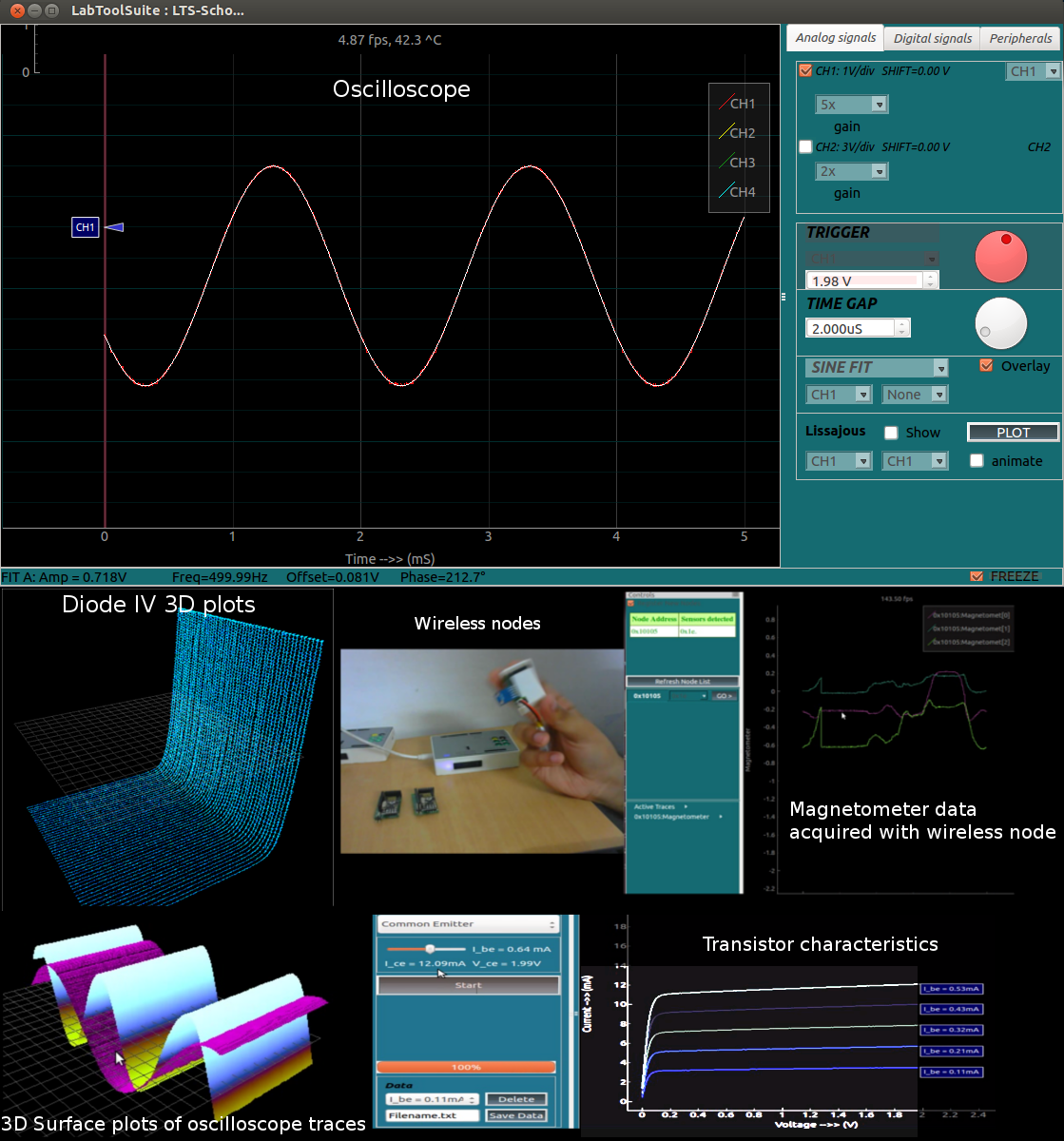
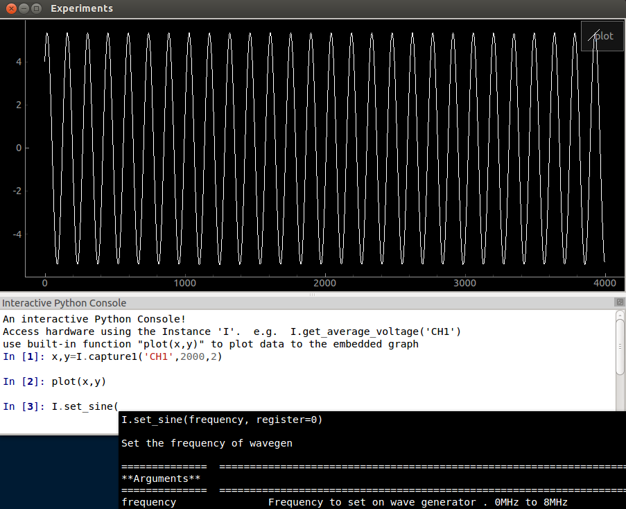
If you're open to trying a few simple lines of code, the console app features an embedded iPython console that autocompletes as well as displays documentation. It also has a ready to use graph that's accessible with a single function call.
As far as developing experiment specific apps is concerned, a few are ready, and a common framework has been developed in order to facilitate contributions by reducing code sizes.


____Is it damage proof?

Users will often make wrong connections, and the design must withstand reasonable assaults.

A few measures...

Read more »

  • 1 × PIC24EP256GP204 Microprocessors, Microcontrollers, DSPs / Microcontrollers (MCUs)
  • 1 × MCP2200 Electronic Components / Misc. Electronic Components
  • 1 × ESP8266 WiFi option
  • 1 × NRF24L01+
  • 1 × MCP6S21 Semiconductors and Integrated Circuits / Misc. Semiconductors and Integrated Circuits

View all 31 components

  • ESP8266:Using the JeeLabs transparent TCP-UART bridge

    Jithin11/10/2015 at 05:31 0 comments

    Everyone on this site is familiar with the ESP8266 module, and I'm grateful for the community effort towards developing application software. In particular, the ESPHTTPD web server, and the Transparent WiFI-UART Bridge ( Based on the former, and featured on the hackaday blog recently ) have been quite useful for me.

    With very slight modifications, the JeeLabs software can be used to turn an ESP-13 module into a TCP-UART replacement for the MCP2200 USB-Serial convertor, thus enabling wifi operation.

    The code running on the ESP hosts configuration pages on port 80, and port 23 can be used to telnet into it and use it as a TCP-UART bridge.

    On the PC side of things I'm using Python sockets to R/W to the vLabtool via the ESP8266.

    fd = socket.socket(socket.AF_INET, socket.SOCK_STREAM)
    fd.connect(('192.168.1.4',23)) # I have configured ESP to connect to my NETGEAR Router
    fd.settimeout(1.0)
    
    fd.send('xyz')  #sending
    print fd.recv(10) #receiving. In case of large packets, use multiple receive calls until the expected number of bytes have been received, because this function may timeout and return partial data.

    On the vLabtool side, nothing changes except a jumper position. The ESP supports the 1MbPS BAUD used by the MCP2200, so even firmware changes were not required.

  • Documentation, and interactive help

    Jithin08/20/2015 at 17:32 0 comments

    Documentation for the python module is generated with sphinx, and is bundled with the source. It's also hosted online at pythonhosted.org/vLabtool/
    In addition to this, the experiment framework has been modified to display a custom webpage for each experiment.

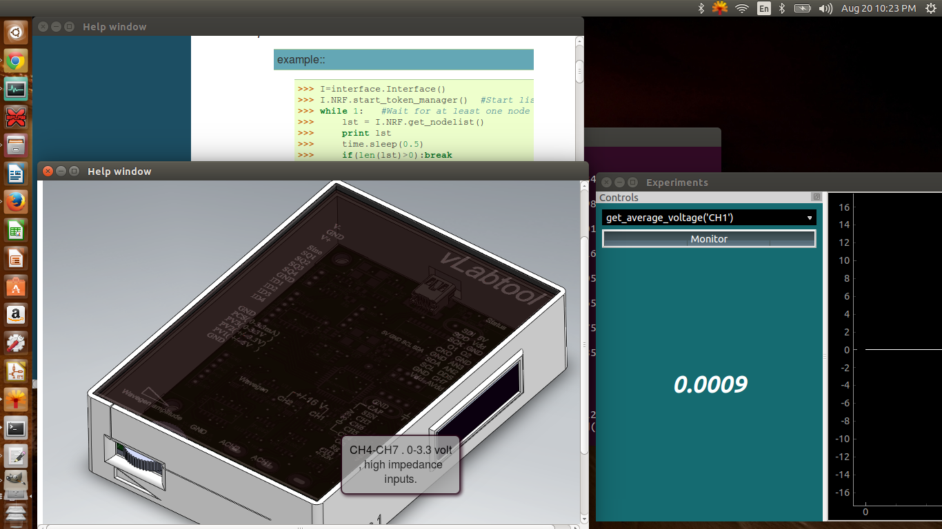
    There is also an imagemap of the vLabtool that shows tooltips on mouseover on various regions


    The interactive tooltips are made with CSS and HTML, and I learnt this from http://www.websitecodetutorials.com . The webpage is embedded using QtWebKit.
    Here's a shortened example of my code for that map if you want to implement something similar.

    <!DOCTYPE HTML><html><head><meta charset="UTF-8"><title>Image Map for the vLabtool</title> 
    
    <style type="text/css">
    body{text-align:center;}
    h2{position:absolute;top:0;left:0;font-size:25px;margin:10px 0 0 10px;}
    
    #map {
    position:relative; height:620px; width:800px; margin:0px auto; background:url('_images/SWrender.png');}
    
    a:hover {
    visibility:visible; /* Fixes IE6 Bug */
    }
    
    .wavegen_amp { position:absolute;
    left:96px;top:385px;width:100px;height:60px;
    text-decoration:none;color:#000;
    } 
    
    .wavegen { position:absolute;
    left:270px;top:300px;width:40px;height:40px;
    text-decoration:none;color:#000;
    } 
    
    
    .wavegen_amp span ,.wavegen span{ 
    position:absolute;
    left:-999em; 
    opacity:.8; /* FX/Opera/Safari/Chrome */
    -ms-filter:"alpha(opacity=80)"; /* IE8 */
    filter:alpha(opacity=80); /* IE6/IE7 */
    border-radius:8px;
    box-shadow:#201 2px 2px 6px;
    } 
    
    .wavegen_amp:focus span,.wavegen_amp:hover span ,wavegen:focus span, .wavegen:hover span{
    left:00px;
    top:30px;
    width:150px;
    padding:10px;  
    border:2px solid #201;
    background:#aaa;
    }
    
    </style> 
    
    
    </head><body>
    <span>Mouse over for details</span>
    <div id="map">
    <a href="#" class="wavegen_amp"><span>Amplitude control for the waveform generator</span></a>
    <a href="#" class="wavegen"><span>Programmable waveform generator output. eg. set_sine(3000.25)</span></a>
    
    </div>
    
    
    </body></html>
    

  • System Diagram & State of development

    Jithin08/16/2015 at 06:27 0 comments

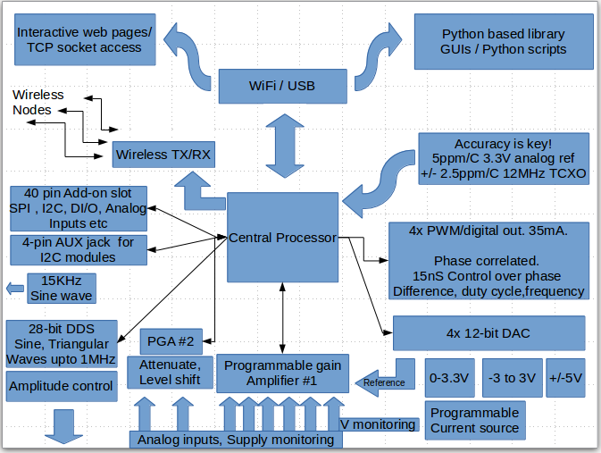
    Flow Chart

    What works?


    2-channel oscilloscope with a variety of different calibrated inputs
    +/-5V , 28-bit waveform generator with manual amplitude control.
    15KHz sine wave generator
    Programmable voltage sources(1-3) , programmable current sources.
    4-channel Logic Analyzer.
    Frequency counter. Tested Up to 32MHz.
    4-channel , phase correlated PWM outputs. Servo motor control.
    I2C, SPI expansion bus.
    Capacitance Measurement.
    Time interval measurement.

    NeoPixel output.
    24-bit ADC add-on.
    Wireless nodes:
    ADC
    I2C interface


    A variety of Python based Apps.


    What doesn't?

    WiFi mode . This has only been tested vaguely with the SDK9.2, and has been documented as a different project.
    It's not an active feature for now.


    What needs improvement?


    DAC calibration routines currently do not store calibration values to flash. They use nominal values, and non-linearity errors up to 10mV have been observed on the 0-3.3V programmable voltage source.


    pF range Capacitance measurement routines with the CTMU need to be calibrated.


    Standalone Mode is a work in progress, and some form of user input switch which can be added at minimum cost needs to be thought out. This mode also does not load calibration constants, and uses nominal values for scaling.


    The android app is also a work in progress.

    Packaging: Injection Moulded Cases to be manufactured


    Pending jobs


    WiFi support.

    Android App.

    A better framework to encourage user contributions.

    Support for a wider array of Add-on modules ranging from Breakout boards to Lock-in amplifiers.

    Developing an array of innovative experiments, and prove how powerful such an architecture can be.

  • On Android

    Jithin08/14/2015 at 20:00 0 comments

    Adding android functionality will mean instant portability for the unit. This will obviously mean that the user won't have the freedom to easily write their own code, but useful apps such as oscilloscopes, and control panels can be coded.

    ttyACM devices such as the vLabtool are supported by a variety of android phones and tablets with USB-OTG support.

    A basic communication test has been carried out, and further development has been pushed down on the priority list.


  • Calibrating the DACs ( Programmable voltage sources)

    Jithin08/13/2015 at 08:22 0 comments

    DACs have non-linearities that are repeatable, but are not usually periodic. Hence, generating a single calibration polynomial is difficult (At least up to a few orders ). A lookup table is the general solution for making an accurate programmable voltage source. Read more about INL errors here

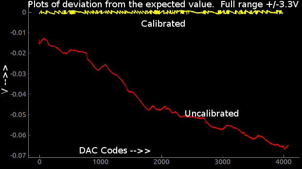
    The following image shows the deviation of one of the programmable voltage sources (resolution 1.6mV. +/-3.3V range) from the expected value(red trace) , and the accuracy of the same post-calibration(yellow trace ). The PIC has copious amounts of flash, and lookup tables and calibration constants can stored in it and loaded by Python upon initialization.

    The overall slope and offset is caused by the amplifying op-amp and corresponding resistors, and can be fixed with a second order polynomial easily.

    The jagged shape however, is a property of the DAC itself, and is corrected using a lookup table that stores the error in each code in terms of number of codes to skip forward/backward in order to achieve the highest resolution without compromising on accuracy.

    *As of this writing, the DAC calibration data is being loaded from text files for testing. They have not been written onto flash memory for the three units I've shipped to SupplyFrame for the Best Product Prize.

  • Bill of Materials

    Jithin08/12/2015 at 19:14 1 comment

    For developing the prototypes, I've sourced parts from a variety of dealers, but for the sake of uniformity, the following table has been generated with most prices obtained from element14, with a few exceptions.

    Total Price : $47

    Package Designation Quantity rate(INR)
    Price USD
    (100 pcs/batch,
    Element14 )


    SOIC-8-N MCP1725 1 40
    0.63
    SOIC-20-W MCP2200 1 130
    2.06
    TQFP-44 PIC24EP64GP204 1 350
    5.56
    SOIC-8-N TL082 4 10
    0.63
    MSOP-10-0.5mm-hand AD9833 1 625
    9.92
    SOIC-8-N 6S21 1 70
    1.11
    SOIC-8-N REF196 1 205
    3.25
    MSOP-10-0.5mm-hand MCP4728 1 125
    1.98
    SOIC-14_N LM324 1 10
    0.16
    SO-16-N MCP6S28 1 135
    2.14
    SOIC-14_N 74HC126 1 10
    0.16
    SOT-23-6 TC1240A 1 50
    0.79
    SOIC-8-N ICL7660 1 20
    0.32
    SOIC-8-N LM358 1 10
    0.16
    SM5050 WS2182 1 10
    0.16
    SO-16-N CH340G(option) 1 0
    0
    ESP12 ESP8266(option)
    0
    0
    fox924 FOX924B 1 150
    2.38
    NRF24 NRF 1 50
    0.79
    Crystal_HC49-U_Vertical 12MHz 1 5
    0.08
    Crystal_HC49-U_Vertical 8MHz 1 5
    0.08
    Fuse_SMD1206_Reflow 0.5A 1 7
    0.11
    SOT-23-EBC 2N3906 1 2
    0.03
    Diode-smd 1N4148 1 1
    0.02
    Diode-smd 4V7 2 1
    0.03


    0
    TantalC_SizeC_EIA-6032_Reflow 100u 4 10
    0.63
    myTantalC_SizeA 33u 2 7
    0.22
    myTantalC_SizeA 10u 1 2
    0.03
    C_0805 10u 1 2
    0.03
    C_0805 4u7 2 2
    0.06
    myTantalC_SizeA 1u 2 2
    0.06
    C_0805 0.1u 26 0.2
    0.08
    C_0805 .01u 3 0.2
    0.01
    C_0805 15pF 4 0.2
    0.01
    C_0805 3p3 2 0.2
    0.01


    0
    R_0805 1E 1 0.1
    0
    R_0805 27E 2 0.1
    0
    R_0805 100E 9 0.1
    0.01
    R_0805 1K 7 0.1
    0.01
    R_0805 1.2K 1 0.1
    0
    R_0805 5K1 2 0.1
    0
    R_0805 10K 22 0.1
    0.03
    R_0805 20K 1 0.1
    0
    R_0805 51K 1 0.1
    0
    R_0805 200K 2 0.1
    0
    R_0805 1M 2 0.1
    0


    0
    2mm-socket Chx 6 5
    0.48
    MYPin_Header_Straight_2x10 CONN_02X10 1 10
    0.16
    Pin_Header_Straight_1x10-oval Analog I/O 1 10
    0.16
    Pin_Header_Straight_1x10 DIO 1 10
    0.16
    myPin_Header_Straight_1x06-oval CONN_01X06 1 6
    0.1
    Pin_Header_Straight_1x03 V+/V- 1 3
    0.05
    slider-pot slider 1 10
    0.16
    aux-4pin-smt I2C 1 20
    0.32
    myUSB_MINI_B USB-MINI-B 1 10
    0.16
    Jumpers 1E 7 0.1
    0.01
    PCB pcb 1 200
    3.17
    Cabinet box 1 500
    7.94
    Cable USB-AtominiB 1 30
    0.48


    47.09

    The total cost excluding shipping stands at less than $50.

    *Optional components marked as zero value.

  • Testing on Raspberry Pi

    Jithin08/11/2015 at 20:34 0 comments

    This project was originally envisioned as RPi2 specific, and prototypes were developed which included the 40-pin header on the vLabtool itself. However, it was later decided to stick to USB, and make the software work with the RPi2 since it has 4 USB ports, and one can be dedicated to the vLabtool.

    Some problems were encountered, and deemed necessary a few firmware changes. The receive buffer of the RPi is much smaller than full blown desktops, and this caused overflows, and data loss. The software has to bring large datasets after splitting them into smaller chunks.

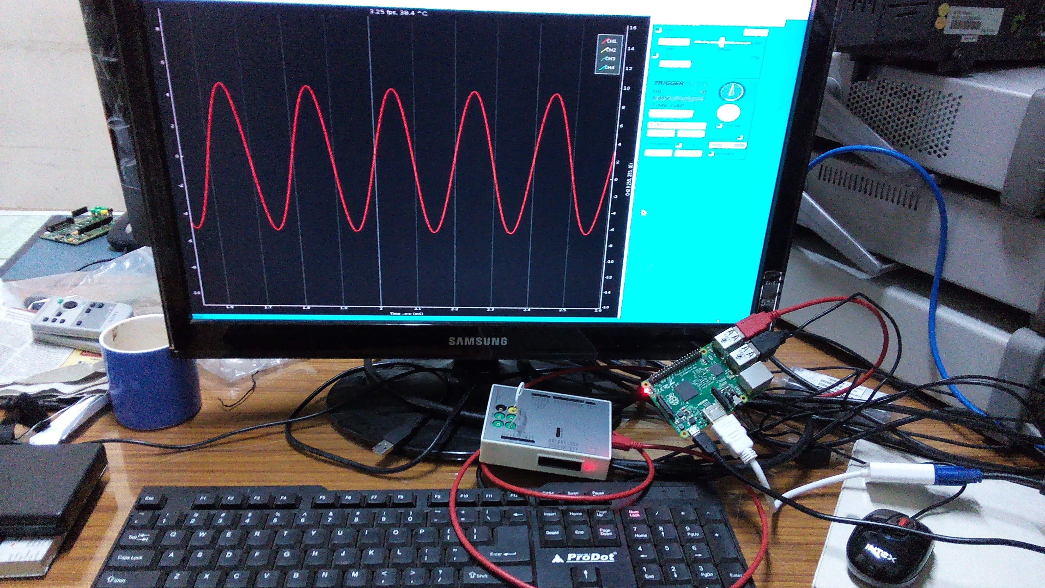
    No detailed testing has been carried out yet, and here's a picture of the oscilloscope GUI running on an RPi2.

  • A few basic electronics experiments. With GUIs

    Jithin08/11/2015 at 19:55 0 comments

    Filter study

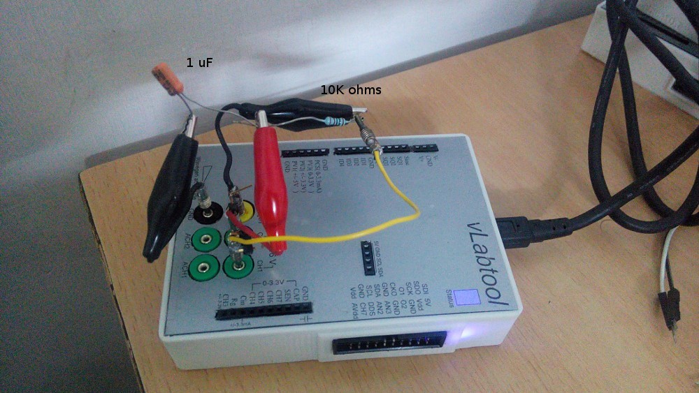
    A simple low-pass RC filter was made with a 10K resistor and 1uF capacitor. The input was taken from the programmable sine wave generator, and simultaneously monitored via CH1 . The output(midpoint of R and C) was also monitored via CH2.
    Frequency was swept from 10Hz to 500Hz, and the amplitude and phase plots are shown

    Photograph of the setup:

    Diode IV characteristics

    A 4148 diode's IV characteristics are plotted.
    Input is taken from a 0-3.3V DAC (PVS3) , and fed to a 4148 diode via a 1K resistor. The other end of the diode is grounded via a current to voltage convertor.

    IV plots are obtained by plotting the voltage across the diode versus the current

  • Monitoring low amplitude outputs via CH3

    Jithin08/10/2015 at 21:54 0 comments

    CH3 is specified as a +/- 3.3 V analog input with up to 32x programmable gain.

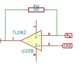
    However, the schematic for the input signal processing stage looks like this

    *A 10MOhm pull down resistor is also present on CH3, and is not shown

    This functions as a unity buffer if Rg is left floating, and CH3 is calibrated under such circumstances. But if the user isn't satisfied with the +/-100mV range at 32x PGA, and wishes to obtain an arbitrarily high gain(subject to noise considerations) , then they may ground Rg via an externally plugged in resistor. The gain will now turn into the familiar formula for a non-inverting amplifier (1+Rf/Rg . Where Rf=10K , Rg=user configured)

    HB100 Doppler radar output monitoring

    Among many other uses, this functionality was used to add another 10x of gain to the 32x internal gain in order to monitor the output of an HB100 doppler radar. The output of this radar is an analog signal whose frequency is a function of the velocity of the reflecting object.

    Here's a video of the test

  • First attempt at a 3D printed case

    Jithin08/05/2015 at 17:51 0 comments

    3D printing is a fantastic tool to rectify errors before investing in an injection mould.

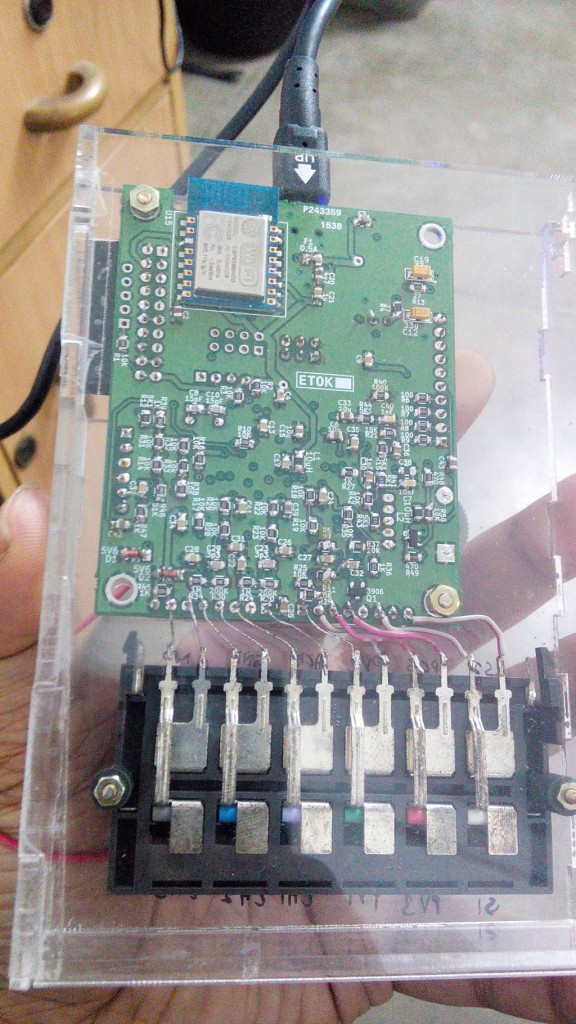
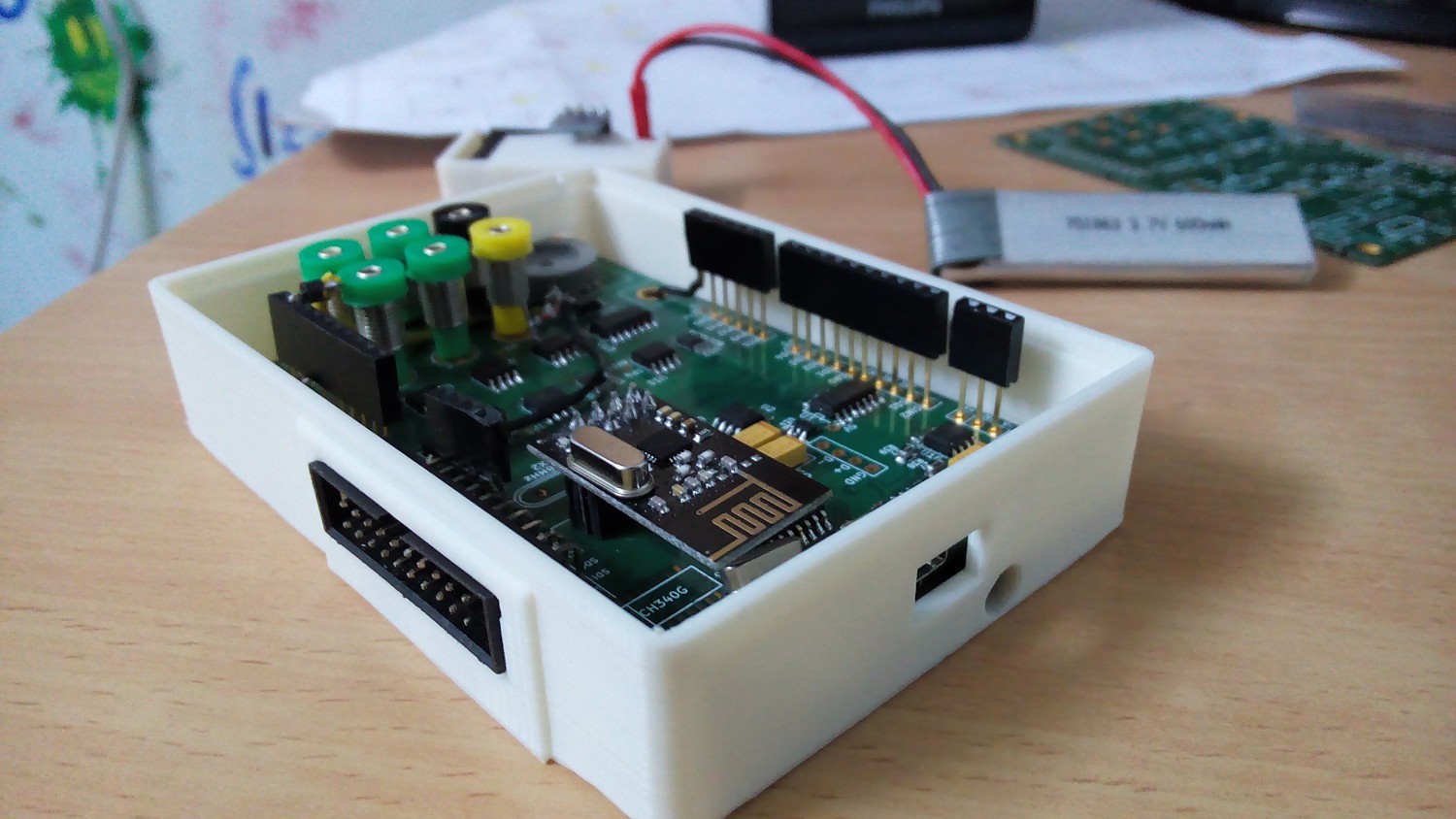
    Here are some of the prints I got made from the Maker's Asylum, New Delhi . The lid will be a laser cut acrylic sheet with appropriate markings for all the connectors, but it isn't ready yet.

    Image: Enclosure for the vLabtool. Slight errors were found, and a revised design has been prepared

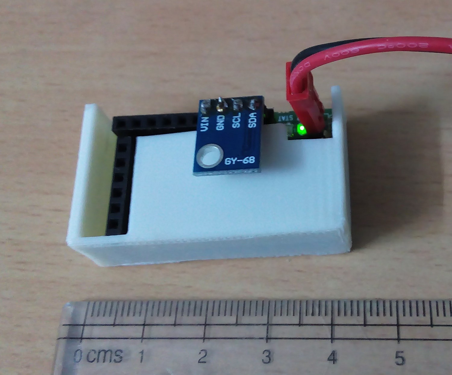
    Image: A wireless node inside its case. An altimeter has been plugged into it.

View all 19 project logs

  • 1
    Step 1

    The device will be available in packaged form, and users do not have to worry about soldering components onto PCBs.

    However, for users wishing to overwrite the default firmware, and repurpose the board, please refer to the schematics.

  • 2
    Step 2

    SOFTWARE.

    -> What Platforms are recommended?

    The toolchain has been developed and tested on Ubuntu versions>=12.04 . It has also been tested on Raspbian Wheezy.

    -> Installing the toolchain [ Debian packaging pending . I'm sorry you'll have to go through this]

    Installing dependencies (Might be incomplete. Please send a PM about missing dependencies ):

    sudo apt-get install python-qt4 python-opengl python-qt4-gl 
    python-sip python-scipy python-numpy ipython-qtconsole 
    python-setuptools
    sudo easy_install pyqtgraph


    A) From Github ( *Recommended for now)

    git clone https://github.com/jithinbp/vLabtool.git
    cd vLabtool
    sudo python setup.py install
    B) From PyPI

    sudo easy_install vLabtool

    -------- The above steps install the Python module as well as several Apps that can be accessed directly from a shell.

    Current list: vLabtool-scope, vLabtool-stream, and several others, all prepended with 'vLabtool' .

    * easy_install fails to install the permissions file 'proto.rules' to a custom location. In the absence of the rules file, the user will need to manually configure permissions for /dev/ttyACM devices, or run all apps as superuser. So running setup.py from a local copy of the software is recommended.

  • 3
    Step 3

    Testing the graphical apps first

    open a shell (terminal, or ctrl-alt-t) , run the following

    vLabtool-scope
    This fires up the oscilloscope program which also includes the logic-analyzer, and several widgets to control voltage sources, waveform generators etc.


    Error?

    Check the USB connection first.
    If that fails, try running the app in super-user mode

    sudo vLabtool-scope
    If the above succeeded, then it's a permissions issue. Please refer to the previous step, and install the toolchain from source [github step].


    You may also manually copy the rules.proto file to /etc/rules.d/rules.proto, and restart udev.

    sudo udevadm control --reload-rules
    sudo udevadm trigger

    The following video shows how to use the analog functions . * Clicking on the 'Digital Signals' tab will switch the application to Logic Analyzer mode, and you will need to return to the Analog Section for this demo.

    For the digital section, select the peripherals tab, and click on the 'update' button. This sets a 500Hz, 50% PWM on SQ1,SQ2,SQ3,SQ4 . Connect these to the digital inputs (ID1, ID2 , ID3, ID4 ) , and check them out by clicking on the 'digital signals' tab. Right click and drag on the plot for zooming along a particular direction. Here's a demo video:

    The 'EVERY EDGE' setting on the logic analyzer is not valid in multi-channel mode if the first signals on any of the channels rise within 200nS of start time, or the trigger signal. If this is the case, please select 'EVERY_RISING_EDGE' or 'EVERY_FALLING_EDGE' to verify the data.

View all 5 instructions

Enjoy this project?

Share

Discussions

Robert wrote 11/18/2015 at 21:13 point

Take my money too! This would make circuit analyzing a cake walk. 

  Are you sure? yes | no

Jithin wrote 11/12/2015 at 16:28 point

Thank you for your encouragement! I'm trying to get it to market.

  Are you sure? yes | no

Matthew Gingerich wrote 11/11/2015 at 05:12 point

Take my money please

  Are you sure? yes | no

Similar Projects

Does this project spark your interest?

Become a member to follow this project and never miss any updates