 Jithin
UPDATE(11-Aug)
First, the results of the calibration!
Random values are input to CH1, and CH3 of the vLabtool, and are simultaneously monitored via a KEITHLEY2100 DMM in order to highlight the accuracy, and noise levels of the different input channels. The DMM seems to add noise to the voltage source, and this is highlighted towards end of the video, wherein one can see that disconnecting the DMM improves the signal quality.
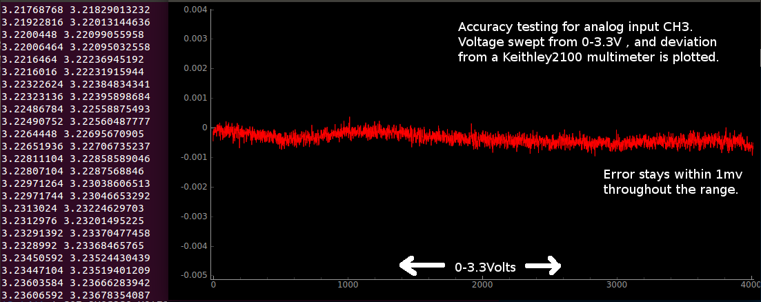
Sample test results for CH3. a 0-3.3V sweep was generated with a 12-bit DAC, and the errors were plotted
When it comes to digitizing analog levels, a number of factors prevent the output codes of the ADC from corresponding perfectly with the input voltage. Even if one somehow reduces noise levels to far below the resolution of the ADC, non-linearity issues as shown in the following image will persist. And these are inherent to ADCs.
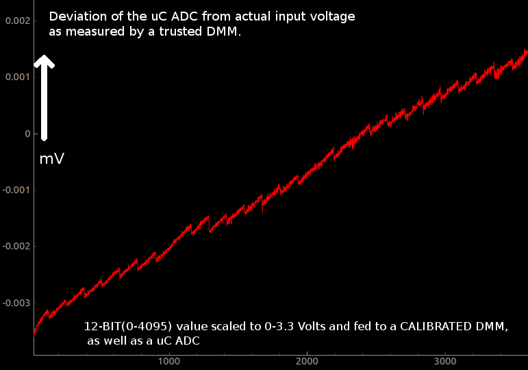
For obtaining the data shown in the above picture, things were kept simple, and no input buffers/gain stages were used.
The output of a DAC was fed directly to an analog input, and the same voltage was also monitored using a calibrated 24-bit voltmeter.
Therefore, if the reference voltage of the ADC (3.3v) does not change, this pattern should be easily repeatable. In order to ensure that, the vLabtool uses a 3.3V voltage reference (REF196) which will stay consistent to within a few ppm over a wide temperature range. The Vref does however, have an initial offset up to 10mV which can be trusted to not drift more than the specified accuracy.
How does one calibrate the uC ADC?
A) The easiest way would be to record the deviations for each input code, and save them in a lookup table. Since the resolution of the ADC is only 12-bits, you'll have a lookup table with 4096 entries. If each entry is a byte, you'll need 4kB of storage.
* In the picture shown , the resolution appears to be much better than 12-bits at 0-3.3V (theoretical resolution = 3300./4096 mV) , and this is the result of oversampling .
B) Another approach would be to simply fit the curve with a finite polynomial, and use the equation for calibration. However, the arbitrary non-linear staircase pattern has proven to be very hard to approximate to an equation.
Here's a polynomial fit of the above. A second order polynomial was generated using numpy.polyfit and numpy.poly1d.
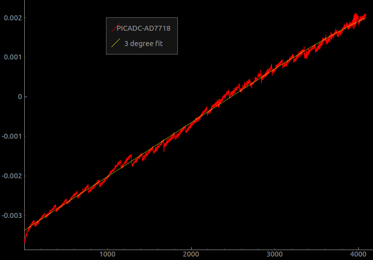
What one could do , is store the fitting polynomial, as well as the deviations from the fitting polynomial.
And a two step calibration can then be applied to obtain a pretty accurate 12-bit ADC performance from your uC.
Will one have to store calibration tables for each analog input (most uC have multiple analog inputs)?
Not likely. Each input is usually routed to the same analog to digital convertor internally via a multiplexer (refer to the datasheet).
So in summary, only one table will have to be stored per ADC, and polynomial fitting functions will be required for each analog input in case you're using opamp buffers or other components which introduce predictable slopes and offsets.
What does this mean for the vLabtool?
The vLabtool has several analog inputs with various voltage ranges (+/-16V, +/-3.3V , 0-3V 0-9V ... ) , but after associated analog circuitry ( hopefully all will have only smooth variations from the actual ) , the signals end up at the same ADC. For two-channel, and four-channel capture routines, a total of four sample and hold capacitors are present, and these take a snapshot of the voltage which are then digitized one by one by the same ADC.
Therefore, the approach I have decided to follow, is to store the deviations for the ADC in a 4KB space in the flash memory, as well as polynomial coefficients for each of the various analog inputs.
Preliminary results -
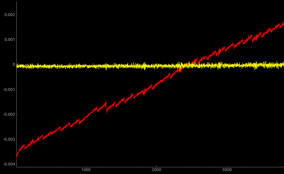
The Red trace represents the deviation of the ADC from the actual input voltage over a 0-3.3V range [ the non-linearities at the ends of the spectrum are not shown]
After the calibration table is applied, one ends up with the yellow trace whose maximum deviation from the actual value stays within 250 micro volts throughout the usable range of the ADC!
If the user requires better resolution and accuracy , they can always choose an add-on board that best fits their needs. The one used as a DMM for the above results was an AD7718 which was calibrated against a KEITHLEY 2100 DMM. The add-on PCB used highly-linear op-amps as buffers, and a REF196 voltage reference. The add-on board has been documented here, and the automated calibration process is here
Calibrating all inputs together, and storing values to flash...
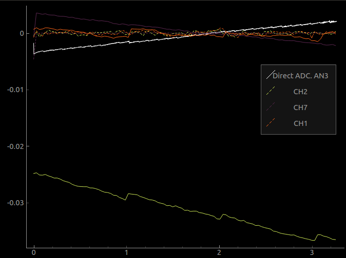
The white trace is data measured from an unbuffered, unaltered analog input , and represents the deviation from the actual value. The sawtooth nature of this curve is the non-linearity of the ADC itself, and will be subtracted from all subsequent readings from the other channels. After this correction, the slopes and offsets of each channel will be stored to flash along with the INL lookup table.
In the figure, the continuous lines represent errors of the uncalibrated inputs, and the dotted lines are generated by applying the two step calibration. Unipolar(0-3.3V) inputs are accurate to less than 200uV, and bipolar inputs (+/-16.5V) are accurate to less than 1 mV after calibration.
if you're wondering why the steps are much wider for CH2, and CH1 (green and orange traces ), it's because the steps are characteristic of the ADC, and these inputs can accept voltages between -16.5V and 16.5V . These voltages are then scaled and shifted into a 0-3.3V range, following which the actual digitization takes place. So a 0-3.3V range for CH1 / CH2 is actually something like 1.65V to 1.97V for a direct analog input like AN3(the white trace) . The step widths will match if you scale by a factor of ten.
UPDATE(11-aug)
Calibrated three units for the Best Product category yesterday, and managed to test the performance against a KEITHLEY2100 multimeter.
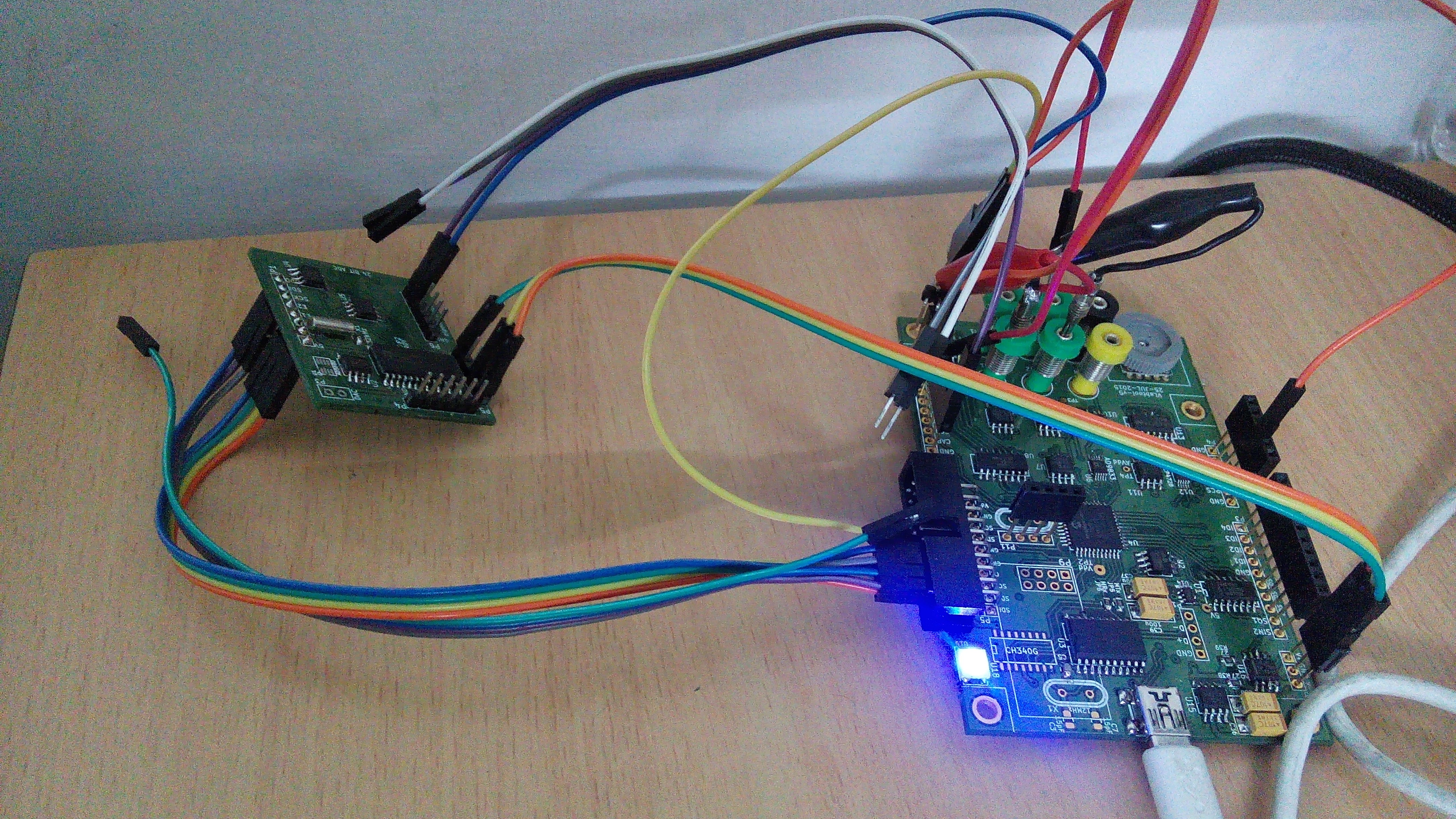
The calibration rig that was used. A custom PCB with an AD7718 24-bit ADC was first built and calibrated against a 6 digit DMM. It was then connected to the SPI portion of the expansion slot of the vLabtool, and used for the calibration process.
The process itself involved sweeping the output of a 0-3.3V DAC and feeding it to inputs CH1,CH2,CH3,CH4, AN3 and the AD7718.
AN3 is directly connected to the uC, and is used to obtain the INL of the ADC. The slopes and offsets of the other channels are calculated after subtracting the INL. The AD7718 serves as the 'actual' value readout.
The calibrated units were then tested against the Keithley2100 connected via USB, and interfaced using python-usbtmc. The test results and video are right at the top of this log
Discussions
Become a Hackaday.io Member
Create an account to leave a comment. Already have an account? Log In.