 Jithin
Flow Chart
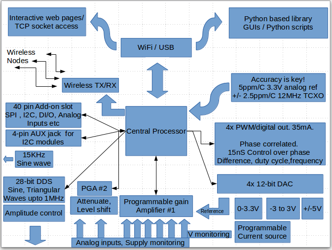
What works?
2-channel oscilloscope with a variety of different calibrated inputs
+/-5V , 28-bit waveform generator with manual amplitude control.
15KHz sine wave generator
Programmable voltage sources(1-3) , programmable current sources.
4-channel Logic Analyzer.
Frequency counter. Tested Up to 32MHz.
4-channel , phase correlated PWM outputs. Servo motor control.
I2C, SPI expansion bus.
Capacitance Measurement.
Time interval measurement.
NeoPixel output.
24-bit ADC add-on.
Wireless nodes:
ADC
I2C interface
A variety of Python based Apps.
What doesn't?
WiFi mode . This has only been tested vaguely with the SDK9.2, and has been documented as a different project.
It's not an active feature for now.
What needs improvement?
DAC calibration routines currently do not store calibration values to flash. They use nominal values, and non-linearity errors up to 10mV have been observed on the 0-3.3V programmable voltage source.
pF range Capacitance measurement routines with the CTMU need to be calibrated.
Standalone Mode is a work in progress, and some form of user input switch which can be added at minimum cost needs to be thought out. This mode also does not load calibration constants, and uses nominal values for scaling.
The android app is also a work in progress.
Packaging: Injection Moulded Cases to be manufactured
Pending jobs
WiFi support.
Android App.
A better framework to encourage user contributions.
Support for a wider array of Add-on modules ranging from Breakout boards to Lock-in amplifiers.
Developing an array of innovative experiments, and prove how powerful such an architecture can be.
Discussions
Become a Hackaday.io Member
Create an account to leave a comment. Already have an account? Log In.