 jean-noel.simonnet
Dahlander motor switch replacement
© J.N. Simonnet – March 2014
Problem statement
This design
is intended as a replacement for a 3-position switch doing 0/3000rpm/6000rpm/0
on a Lurem wood machine
Remember that the kinetic energy varies with the square of the rotating speed, so the machine is designed to spin down freely to zero from 6000 rpm.
The mechanical part of the switch is broken and the switch has to be replaced.
The Lurem machine is no longer supported as the Lurem company has disappeared, and the broken original Dahlander switch cannot be sourced again.
Some
vendors still have spare parts, but none still have stock for the original.
Some of these vendors have switches doing 0/3000rpm/6000rpm/3000rpm/0 without
the mechanical device preventing from going from 6000 to 3000 rpm. As already
mentioned, this is not adequate. Additionally, these sell for around 200 €, and
it is cheaper to re-implement with an Arduino
The
electrical motor is a Leroy-Somer LS100L2
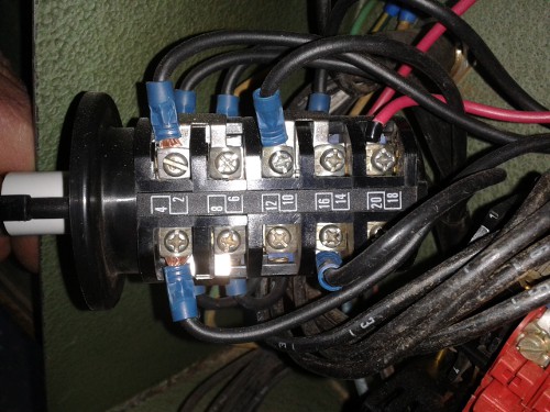
This photo shows the broken switch. You may notice the left hand side which no longer has the original mechanical device preventing backwards rotation.
Dahlander motors
Dahlander
motors
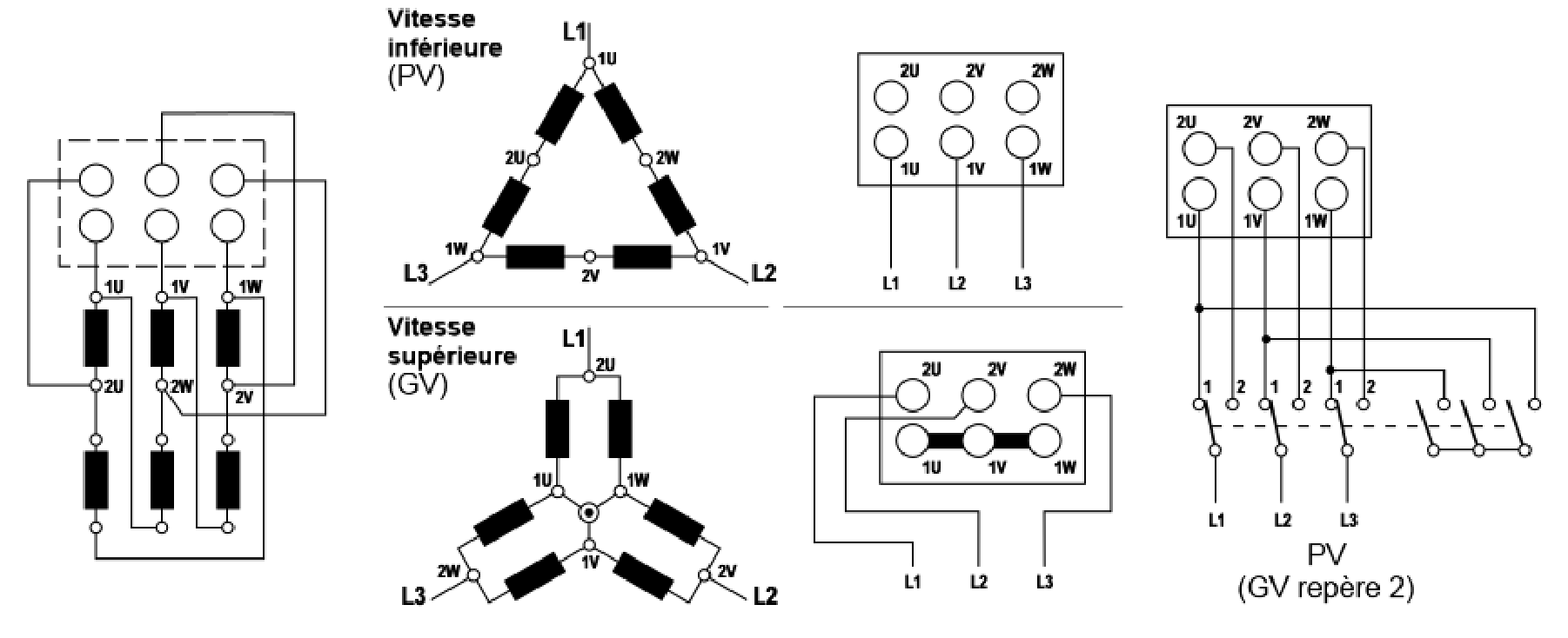
Constant couple model (YY/D)
This is the most common model. It corresponds to a load couple which remains constant with the rotation speed.
Low speed: each winding is fed with U/2 or 190V. Windings are under-supplied, which reduces slightly the available power. High speed: each winding is fed with 220V, the nominal value. Hence the Leroy-Somer LS100L2 motor is rated for 3 kW for the low speed and 3.7 kW for the high speed.
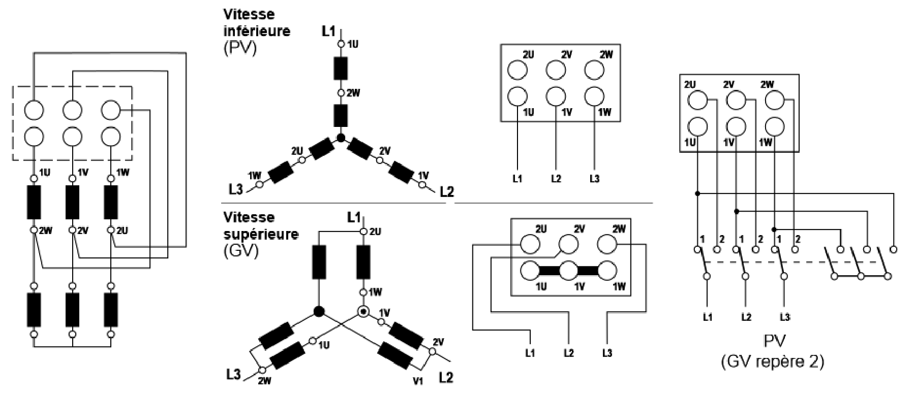
Quadratic couple model (YY/Y)
Quadratic couple means that the load couple varies as a function of the square of the rotation speed, like a fan. Model type is YY/Y.
Each winding receives 220V in high speed mode, and 110V in low speed mode.
Connections to mains
Both models are connected as follows:
- Low speed: U1/V1/W1 to mains 3-phases, U2/V2/W2 unconnected
- High speed: U2/V2/W2 to mains 3-phases, U1/V1/W1 shorted
In the Lurem machine, we have a mechanical speed increase by a factor of 2, as the highest rotation speed one can achieve at 50 Hz is 2850 rpm.
It is important to ensure that the switch from low to high speed does not generate a short-circuit . This is something to watch when implementing the switching with relays, and it implies putting some delays between relay activations/de-activations.
Reference wiring with contactors
Here is the wiring for the two speeds. The implementation makes use of 3 relays.
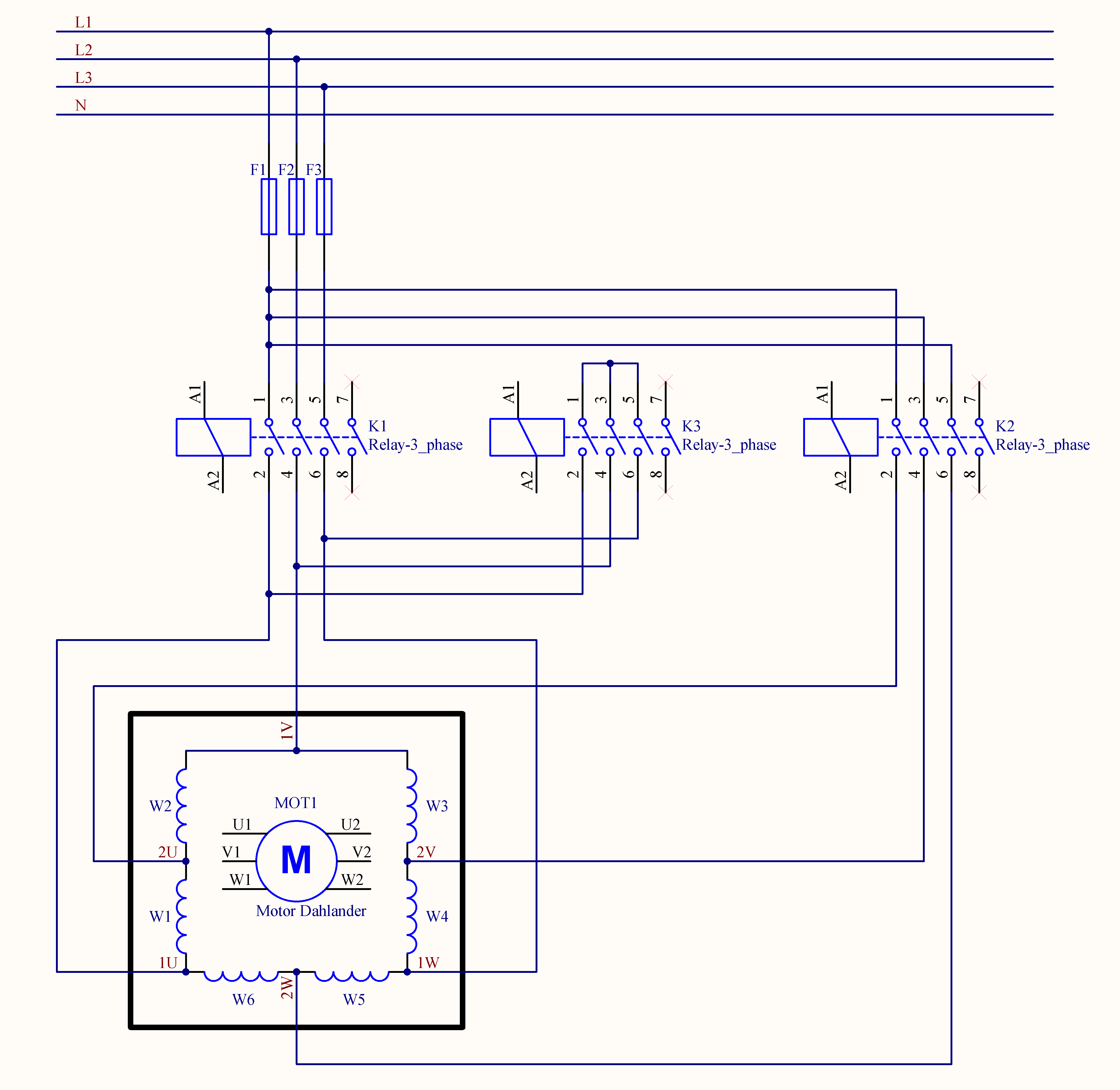
Though the drawing shows a constant couple model, the wiring is actually the same regardless of the actual type:
Overall design
As there is enough room in the existing control box, I have chosen a DIN rail mounting, with a maximum length of 230 mm. The 3 relays will then be DIN rail mounted. I have also selected a 24V DIN rail mount power supply, which will be connected between 1 phase and the neutral to obtain the 220V supply required.
DIN
rail mounting
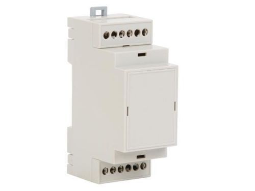
As for the electronics, I have selected a custom DIN rail box. It contains the custom interface board to steer the relas, as well as the Arduino Pro Mini.
The custom box can be seen to the right of the first picture, with a red LED on (Arduino).
Relay
selection
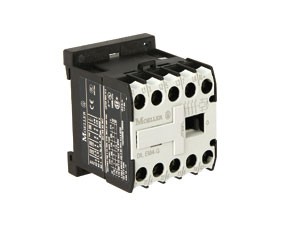
I have chosen Moeller relays which switch 3 phases L1/L2/L3 and also have a 4th contact, which we are going to use for a light indicator. The relay coil is operated at 24V. The light indicators are 24V lights.
These relays consume 2.6W as per their datasheet, which translates to 110 mA coil current. I have measured slightly less than 120 mA when powering the relay from a 24V source, and measured a coil resistance of 205 Ohms, which is consistent.
The contacts are rated for 4KW power, which is appropriate for the Lurem motor, which is 3.7 KW.
The relays can be seen to the left of the first picture.
User
interface: one pushbutton + 2 lamps
The user interface is made of one industrial push button and two lamps indicating which speed is selected: yellow for 3000 rpm, and green for 6000 rpm.
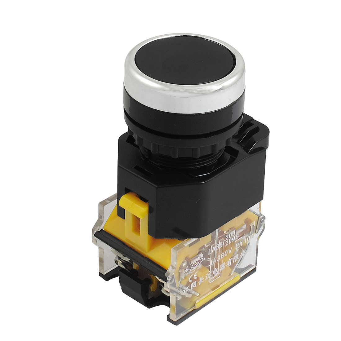
The user pushes the button once; the machine operates at 3000 rpm, the yellow lamp lights. If he pushes a second time, the machine operates at 6000 rpm and the green lamp lights. If pushing another time, all lights go off, as well as the motor.
It is not possible to restart the machine within 10 seconds after we switched it off, so that there is no risk to re-power the machine while rotating at a speed higher than 3000 rpm.
It is also possible to switch off the machine when operating at 3000 rpm, with a long push (>2s) on the push button.
Moving from low speed to high speed, we first disconnect relay 1, wait for 200 ms, activate relay 3 (short-circuit), wait for 200 ms, then activate relay 2.
Yellow LED is connected in parallel with K1 coil, and green LED is in parallel with K2 coil. Their sole purpose is to display the actual speed outside.
Those two lamps are not strictly needed, as it is obvious from the rotation noise which speed we are at.
24V
power supply
I have selected a DIN rail mount power supply providing 24V/1A.It can be seen to the right of the first picture.
 L is
connected to L1, and N requires a mains neutral wire to be brought to the
wiring box, which was not originally the case.
L is
connected to L1, and N requires a mains neutral wire to be brought to the
wiring box, which was not originally the case.
This allows the power supply to be fed with 220V, instead of 380V we get between any two phases.
As the entire setup is going to replace the original switch and this switch is behind a contactor, the power supply will be powered off as and when the corresponding tool is de-activated, ensuring it is not permanently connected to the mains.
Finite state machine
The finite state machine
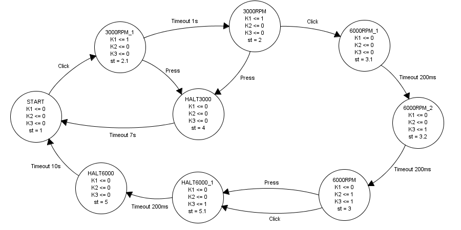
One pushbutton is used to cycle as per the original design: 0-3000rpm-6000rpm-0, with a short push each time (aka 'Click'). Additionally, a long press (> 2s) allows spinning down from 3000 or 6000 rpm to 0.
Timeouts are inserted:
- a 1s spin up timeout preventing any change while the machine is spinning up to 3000 rpm
- a 7s spin down timeout preventing the machine restart while being spun down from 3000 rpm
- a 10s spin down timeout preventing the machine restart while being spun down from 6000 rpm
- 200 ms timeouts inserted between relay changes. This is done so that we are sure we do not have a risk of wrong temporary connection while relays are changing state
The timeouts introduce a security that did not exist in the original switch, so that it is not possible to spin the machine up again while still rotating.
The above
diagram has been produced with fizzim
Which state are we in?
The custom DIN rail box comes with a transparent window which we put to use to see the internal LEDs. The normal sate is the RED LED on, indicating that the Arduino Pro Mini has power, and the Green LED blinks as per the number in the table 2 below.
We blink # times 400 ms, followed by a 1s pause. Just count the number of blinks and you know which state we are in.
Here is the table mapping states :
| Name | # | Machine state |
| START | 1 | Powered up, waiting to start |
| 3000RPM | 2 | Machine operating at 3000 rpm |
| 6000RPM | 3 | Machine operating at 6000 rpm |
| HALT3000 | 4 | Machine being spinned down from 3000 rpm |
| HALT6000 | 5 | Machine being spinned down from 6000 rpm |
States and number of blinks of the Green Arduino LED
Mapping the relay connections to the original switch
The mapping
table
Here is the mapping table:
| Relay | K1 | Q3 | K2 | Q3 | K3 |
| 1 | L1 | 2 | L1 | 2 | COM |
| 3 | L2 | 4 | L2 | 4 | COM |
| 5 | L3 | 13 | L3 | 13 | COM |
| 7 | NC | NC | NC | ||
| 2 | 1U | 5 | 2U | 1 | 1U/5 |
| 4 | 1V | 7 | 2V | 3 | 1V/7 |
| 6 | 1W | 10 | 2W | 16 | 1W/10 |
| 8 | NC | NC | NC | ||
| A1+ | +24V | +24V | +24V | ||
| A2+ | Arduino D3 | Arduino D4 | Arduino D5 |
New design to original switch mapping table
This drawing extract shows the original electrical design around the motor we are going to steer with this new design.
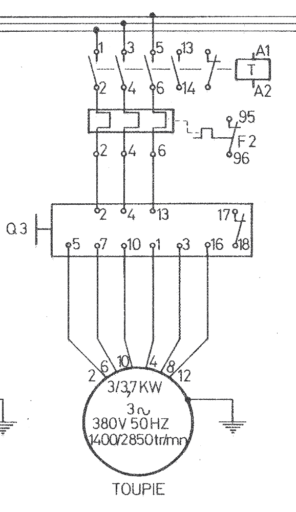
Q3 is the original manual Dahlander switch.
- L1/L2/L3 map to Q3 connections 2/4/13 respectively
- 1U/1V/1W map to Q3 connections 5/7/10.
- 2U/2V/2W map to Q3 connections 1/3/16.
Electronics
design
Because
each relay draws 110 to 120 mA @24V, a BJT interface is required. It is built with a free-wheeling diode in parallel with the relay coil. A 2N2222 with a series resistance of 330 Ohms in the base is sufficient. As for the free-wheeling diode, 1N4148 is sufficient.
Steering relay from Arduino: simulation
The
simulation was done with Tina-TI
Here are the schematics:
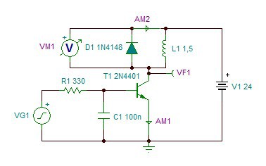
The DIL-EM4-G relay is modeled as a 1.5H inductance in series with a 205 Ohms resistance. These values were measured on the actual relay.
And now the simulation results:
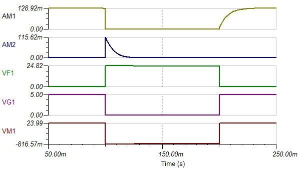
D1 diode sees a maximum current equivalent to the relay current, quickly dropping to zero (depends on the relay coil inductance value and series resistance. Its reverse voltage is the supply voltage (24V).
With these values, a 1N4148 diode which can withstand 200 mA, non-repetitive 500 mA for 1s and has a maximum reverse voltage of 60V, is sufficient for our relays.
As for the transistor, Vce is exposed to an increase of 820 mV, when the diode conducts, and a maximum Ic current which is the relay current, or 130 mA.
We may use:
- A 2N2222, with Icmax of 800 mA, and Vcemax of 30V; its hfe is 50 @ 150 mA, which means Ib of 15 mA is sufficient to saturate the transistor.
- A 2N4401, with Icmax of 600 mA, and Vcemax of 40V; its hfe is 100 @ 150 mA, which means Ib of 8 mA is sufficient to saturate the transistor.
[i] Texas Instruments TINA-TI SPICE simulator: http://www.ti.com/tool/tina-ti
[ii] Linear Technology LTSpice iV: http://www.linear.com/designtools/software/#LTspice
Using an Arduino Pro Mini
We are going to
use an Arduino Pro Mini
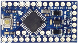
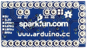
We are only going to use 1 digital input and 4 digital outputs. It receives its power from the 9V supply on the custom board.
It is fitted with a header which can be used to program the device. This interface is needed each time one wants to change the timing parameters, as the only way to adjust is to reprogram the device.
In order to
program it, we are going to use the Arduino USB/serial
Here is how we are going to assign I/O pins :
- D2 – Push button, digital input
- D3 – Relay K1, digital output
- D4 – Relay K2, digital output
- D5 – Relay K3, digital output
Apart from these connections, we also need a GND and a +5V connection from the power supply.
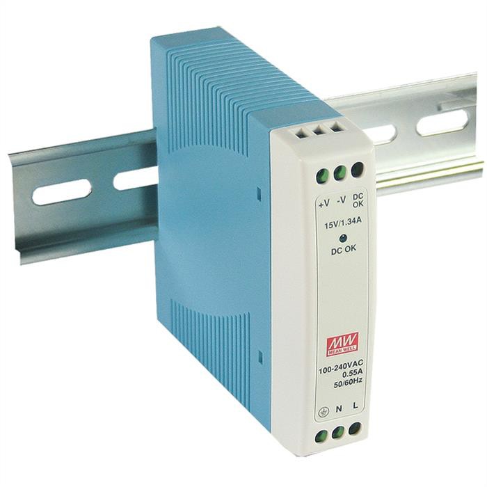
Power supply
We start from a 24V/1A power supply. We will draw a maximum of 300 mA when 2 relays are activated. I have selected a DIN rail 24W Meanwell power supply.
In order not to exceed the built-in Arduino 5V regulator, it is desirable not to exceed 12V for the unregulated power. I have chosen to generate 9V with a linear regulator from the 24V. This regulator and its two capacitors are also present on the custom base board.
Given the low power consumption of the Arduino board, a linear regulator is simple enough, and consumes less space.
Custom
board
This board holds the 3 relay interfaces, the +9V linear regulator and the switch connector.
It is implemented on a piece of stripboard:
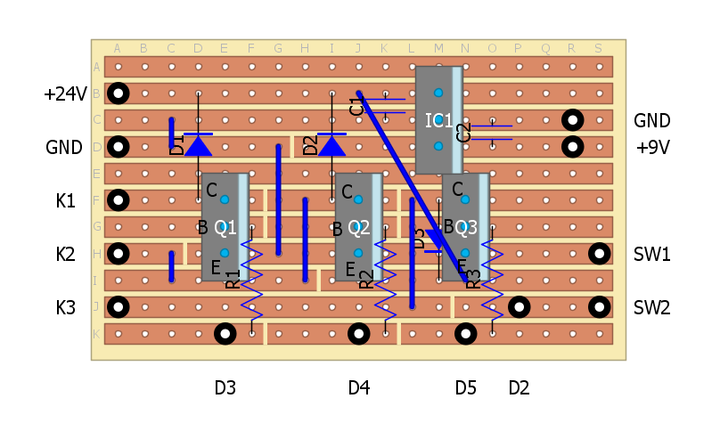
The above board
has been designed with DIYLC
Arduino code
The code essentially implements the Finite State Machine as designed above. The design is essentially based on the OneButton ‘BlinkMachine’ example which shows a good example of implementing an FSM around the button actions.
There are 3 different actions that can be used:
- Click : short press of the button followed by >600 ms idle time
- Double click: two short presses of the button within 600 ms
- Press: a long press of the button (> 2s).
Our design will use ‘Click’ to move between states, with ‘Press’ to abort from where we are currently. ‘Double click’ is not used here.
Timeouts are used to generate events after a fixed amount of time.
Each state outputs (K1, K2, K3) is periodically activated as per the state we are in as part of the ‘loop’ function actions.
The callbacks used by OneButton and SimpleTimer are where we define the transitions between states.
Libraries
used
The code makes use of the OneButton library to detect short and long button press, as this library makes it simple to implement a finite state machine.
See: http://www.mathertel.de/Arduino/OneButtonLibrary.aspx
It also makes use of the SimpleTimer library in order to implement non-blocking delays which call a pre-defined routine when the timeout has expired.
See: http://playground.arduino.cc/Code/SimpleTimer
Additionally, we also use the SyncLED library in order to display current state by blinking the built-in LED on D13. This is for debug purposes.
See: https://code.google.com/p/arduino-library-syncled/
Relative to blinking the on-board LED (D13), we blink the stable state, and this is done through coding stable states with numbers in the 1..15 range, while the sub-state number is coded into the upper nibble. We lose the unstable state number, but the indication is sufficient for our purposes.
Parameters as #define statements
Changing these requires a code recompile and reload, which of course requires a PC and a USB/serial interface.
All pins in use are entered as #define statements:
- SW1 (pushbutton) associated to D2 =2
- K1 (relay) associated to D3 =3
- K2 (relay) associated to D4 =4
- K3 (relay) associated to D5 =5
All timings are also #define statements; values are in ms:
- DELAY_RELAY is the delay between relay activations. Default =200ms.Ensures sufficient time between relay switching to ensure safe operation.
- DELAY_SPINUP is the time taken to spin up the machine @3000rpm. Default = 1s.
- DELAY_HALT3000 is the time taken to spin down from 3000rpm. Default = 7s.
- DELAY_HALT6000 is the time taken to spin down from 6000rpm. Default = 10s.
Additionally, we have two parameters which control the button behavior :
- CLICK_TICKS is the minimum idle time after a single short push to detect a ‘Click’. If two short pushes occur within this time, we detect a ‘Double click’. Default 600ms.
- PRESS_TICKS is the minimum time the button must be pressed to detect a long ‘Press’. Default 2s.
Code structure
Setup function initializes the I/O pins, and the 3 library objects we need. We only need 1 timer object, as the FSM only takes one state at a time. We also attach callbacks needed by the OneButton library to process ‘Clicks’ and ‘Press’ actions.
The loop function deals with the updates to each one of the 3 library states. It is also in charge of applying proper outputs as a function of the state we are in.
Callbacks (OneButton & SimpleTimer) are in charge of managing state transitions. Timeout triggering also happens here. Also the blinking pattern is updated within these callbacks. It could not be put inside the loop function, as it would then get reset at each loop.
Other options which have been explored
The Button
library
De-bounce a
switch
Alternatively,
one could also have used the Arduino Bounce library
As for the
Finite State Machine implementation, what comes built-in the OneButton examples
shows a good enough implementation. Alternative, googling for “finite state
machine Arduino library” yields a few results
Testing
Custom board & relays
Arduino board is unplugged, 24V supply connected, relays wired.
9V Power supply
Power the board. Measure voltage at Arduino power connector: We observe 9V.
Relay drivers
Use a lab power supply adjusted at 5V. GND to the adapter board GND, then touch the D3/D4/D5 connections in turn with +5V. One should observe K1 move + yellow lamp on, then K2 move + green lamp on, then K3 move.
Contact
Ohmmeter connected between GND and the D2 output.
When pressing the pushbutton, resistance drops to less than 1 Ohm.
Arduino
Arduino board is connected through an Arduino USB/serial adapter.
Remove the 24V power supply power, then connect the +9V connector to the Arduino board. Power up again; we should see the red LED on the Arduino Pro Mini board light up.
OneButton library
Edit the SimpleOneButton sketch to change the button connection from pin A1 to pin D2, as this is where our pushbutton is connected. Upload the modified sketch.
Do a fast double click on the pushbutton, you should see the green LED on the Arduino Mini to light up. Do another double click, you should see the green LED turn off.
Now repeat the test with a slow double click (more than 1s between the two presses), the LED will not change state.
Relay steering from Arduino
Edit the SimpleOneButton ketch to change the D13 output to D3. Repeat the above test, relay K1 will successively activate and de-activate.
Repeat the test by changing D3 to D4, then D4 to D5; K2 and L3 will activate.
This verifies that relay steering is OK.
SimpleTimer library
None of the default examples can be used for test purposes.
SyncLED library
Edit the blink_easy sketch, to add a duration parameter of 200UL (200 ms). This is the optimal time to be able to count, and fast enough. You should observe the Arduino green LED to blink 5 times, pause for 1s and repeat.
Bench test the Dahlander sketch (without the 3-phase connections)
Sketch is uploaded. D13 LED blinks once, then pauses for 1s. We are in state 1 (START), waiting for operator commands.
Test normal cycle: 0/3000rpm/6000rpm/0 cycle
Push button
once shortly. Relay K1 is activated and yellow LED is on.
D13 blinks twice, we are in state 2, rotating at 3000 rpm.
Push button immediately, nothing happens. The machine must spin up to 3000rpm before being able to change state (either to stop or to move to 6000rpm).
Wait for 1s (spin up time). Then push button once shortly; relay K1 de-activates, then K3 activates, then K2 activates; yellow LED goes off, green LED is on, and D13 blinks 3 times as we are in state 3; machine rotates at 6000 rpm.
Push button once shortly, relay K2 de-activates, then K3 de-activates; green LED goes off, D13 blinks 5 times, machine is spinning down, and after 10s, D13 blinks once only, we are back to the START state.
Test forced stop @3000 rpm
‘Click’
once shortly. Relay K1 is activated and yellow LED is on.
D13 blinks twice, we are in state 2, rotating at 3000 rpm.
‘Press’ button once for more than 2s, before 30s. Relay K1 goes off, as well as the yellow LED. D13 blinks 4 times. Then after 7s, D13 blinks once, we are back to the START state.
We just stopped the machine while spinning down.
‘Click’
once shortly. Relay K1 is activated and yellow LED is on.
D13 blinks twice, we are in state 2, rotating at 3000 rpm.
‘Press’ button once for more than 2s, after 1s. Relay K1 goes off, as well as the yellow LED. D13 blinks 4 times. Then after 7s, D13 blinks once, we are back to the START state.
We just stopped the machine which had reached 3000 rpm.
Test forced stop @6000 rpm
‘Click’
button once. Relay K1 is activated and yellow LED is on.
D13 blinks twice, we are in state 2, rotating at 3000 rpm.
‘Click’ button immediately, nothing happens. The machine must spin up to 3000rpm before being able to change state (either to stop or to move to 6000rpm).
Wait for 1s (spin up time). Then ‘click’ button once; relay K1 de-activates, then K3 activates, then K2 activates; yellow LED goes off, green LED is on, and D13 blinks 3 times as we are in state 3; machine rotates at 6000 rpm.
‘Press’ button once, relay K2 de-activates, then K3 de-activates; green LED goes off, D13 blinks 5 times, machine is spinning down, and after 10s, D13 blinks once only, we are back to the START state.
Connect to the real motor and mains
At this stage, we are now ready for real life connection, but before we jump in and in order to avoid issues which can quickly be destructive, we first need to identify the mains connections L1/L2/L3, and the 1U/1V/1W, 2U/2V/2W connections.
Identifying the mains connections
Start first with the main switch in the on position, and the speed switch in the 0 position.
Measure voltage between pairs of wires until finding 380V. Where we have the live voltage is where we have the main inputs. We are left with 6 wires to identify, which correspond to the motor connections.
There is possibly a simpler way when the machine electrical drawing is available.
This drawing shows that we have the following connections (numbers refer to the original Dahlander switch connections : L1 = 2, L2 = 4, L3 = 13
Odd finding : when on the low speed position, L1 and L2 are connected to motor connections 5 and 7 respectively, but 13 which ought to be connected to 10 display a 50 Ohms resistance. The motor rotates, but probably with a reduced power by 1/3 as we miss one phase.
Identifying the motor connections
Start first by ensuring the machine main switch is off.
Verify voltage across each pair of phases to ensure it is 0.
With the switch in the 6000 rpm position, check which wires are shorted together; this group is the 1U/1V/1W group, the other 3 are 2U/2V/2W. Position on the switch is also a good indication as on can expect the wire order to be same between both groups, also matching the order of phases.
Please note that respecting the phase order also matters for the direction of rotation.
With the switch on the 0 or 3000 rpm position, measure resistance between each pair of wires. We should get a resistance of R between 1U/2U, 2U/1V, 1V/2V, 2V/1W, 1W/2W, 2W/1U.
We measure 3.6 Ohms between consecutive connections.
Now if we refer to the drawing while in low speed mode, we should have the following connections :
- 1U – 2U – 1V – 2V – 1W – 2W – 1U
- 5 – 1 – 7 – 3 – 10 – 16 – 5
But we get
- 5 – 1 – 7 – 16 – 10 – 3 – 5
- 1U – 2U – 1V – 2W – 1W – 2V – 1U
Odd finding: Wires 3/2V and 16/2W are swapped; need to swap them in the above mapping table.
It apparently does not prevent the motor to run but possibly creates an issue with the power delivered.
We need to verify actual switch to motor connections to be sure.
As the switch has been swapped a few times, it is possible that two wires got swapped in the process.
With the switch on the 6000 rpm position, measure resistance between 2U and 1U/1V/1W, then 2V, then 2W and the common point. We should get R/2.
We measure 2.2 Ohms. So R = 4.4 Ohms. 5/6R = 3,7 Ohms, consistent with the 3.6 Ohms we measured.
Final connections & tests
Label wires as per the names identified and connect them to the corresponding relay connections. Also connect the 3 phases to the relay input.
Ensure the 24V power supply is connected to L1 and N.
We are now ready for a real test.
When powering up, if machine rotates in the wrong direction, just swap two of the phases at the input.
BOM
Here is the BOM corresponding to my implementation:
| Item | Manufacturer | Part number | Supplier | Quantity | Cost |
| DIN rail (240 mm) | Castorama | 1 | 7,00 | ||
| DIN rail 24V power supply | Meanwell | MDR-20-24 | eBay (it_tronics) | 1 | 25,30 |
| Power relays | Moeller | DIL EM4-G | eBay (mago-shop_de) | 3 | 53,65 |
| Custom DIN rail box | eBay (wbteam) | 1 | 10,41 | ||
| Green 24V LED | eBay (wbteam) | 1 | 5,60 | ||
| Yellow 24V LED | eBay (wbteam) | 1 | 5,64 | ||
| Industrial push button | eBay (niceicon) | 1 | 4,34 | ||
| Arduino Pro Mini | eBay (comelili) | 1 | 3,00 | ||
| Misc components | 5,00 | ||||
| TOTAL | 119,94 |
Table 4: Device Bill Of Materials
[2] Arduino is a micro-controller based on AT Mega328 from Atmel, http://arduino.cc/
[3] Emerson/Leroy-Somer, LS motor catalog, http://www.leroy-somer.com/_popup/fr/telechargements/catalogues/catalogue.php?ref=3676
[4] Dahlander constant couple model, http://www.nzdl.org/gsdlmod?e=d-00000-00---off-0gtz--00-0----0-10-0---0---0direct-10---4-------0-1l--11-en-50---20-help---00-0-1-00-0-0-11-1-0utfZz-8-00&a=d&cl=CL2.1&d=HASH01693eebdf3891bea95c4ae7.7.4.2
[5] Dahlander quadratic couple model, http://educypedia.karadimov.info/library/173.pdf
[6] Finite state machine explanation on Wikipedia: http://en.wikipedia.org/wiki/Finite_state_machine
[7] Fizzim is a FREE, open-source GUI-based FSM design tool, http://www.fizzim.com/
[8]This
table was derived from the original wiring diagram on can find http://www.lurem.org/documentation-divers
, ‘Schémas électriques des machines’. The relevant drawing is ‘Schemas
C360-410N France.pdf’ inside the ‘schemaselectriques.zip’ archive.
Refer to page 22 which is the actual reference drawing.
[9] Texas Instruments TINA-TI SPICE simulator: http://www.ti.com/tool/tina-ti
[10] Linear Technology LTSpice iV: http://www.linear.com/designtools/software/#LTspice
[11] Arduino Pro Mini, product page from Sparkfun : https://www.sparkfun.com/products/11113
[12] Arduino Pro Mini page on arduino.cc Web site : http://arduino.cc/
[13] Arduino USB/serial light adapter, http://arduino.cc/en/Main/USBSerial . This one allows for direct plug into the Arduino board. Additionally, it also implements a reset of the board after the code has been loaded.
[14] DIYLC, Do It Yourself Layout Creator, a freeware which can assist in the design of stripboard electronics, http://code.google.com/p/diy-layout-creator/
[15] Arduino Button library, http://playground.arduino.cc/Code/Button
[16] A guide to switch debouncing, http://www.eng.utah.edu/~cs5780/debouncing.pdf
[17] 74HC14 based de-bouncing, http://forum.arduino.cc/index.php?topic=136587.0 . Look for other sources googling for “debouncing switch”.
[18] 555 based switch debouncing, http://abdulrahman-225-vp8.weebly.com/1/post/2012/11/555-timer-switch-debouncing-circuit.html
[19] Arduino Bounce library for switch de-bouncing, https://github.com/thomasfredericks/Bounce-Arduino-Wiring
[20] Possible Finite State machine Arduino libraries : http://en.wikipedia.org/wiki/Finite_state_machine or http://playground.arduino.cc/Code/FiniteStateMachine