 Reed Foster
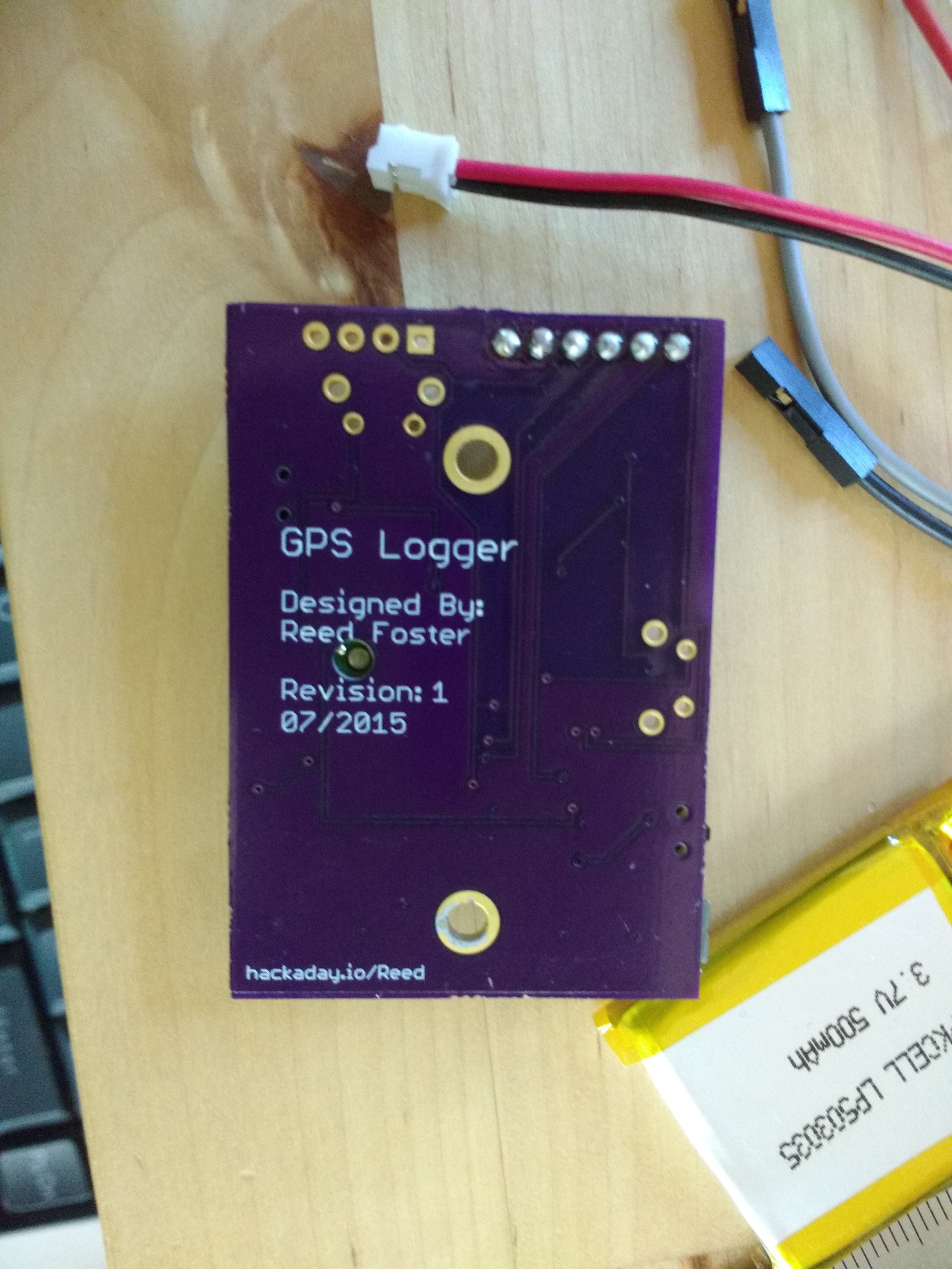
I designed a custom pcb in Eagle CAD and had it manufactured by OSHPark. Below are two images of the board populated with components ordered from mouser. I used a stencil from OSH Stencils to apply a layer of solder paste to the board and placed each component with tweezers. Once the board was populated with all of the components, I carefully placed it in a reflow oven (Black and Decker modified with a controleo oven controller) and pushed "reflow". There were no problems to speak of in the reflow. The components can be found in the folder with the eagle files.
I plan to further improve this design and add a display from friedcircuits.us as well as design the board to fit a specific enclosure. I also am improving the software to put the atmega to sleep and re-configure the GPS to send packets once every 30 seconds. This should dramatically reduce power consumption.
The board files are more for reference and interest than for actual use because a) the board design makes it quite a pita to program the on-chip flash, and b) some of the board is not routed quite properly and some components are unnecessary. You will notice a red wire on the board. This was put in place because I used a ferrite bead to create a filter that I did not really need, and it actually ended up causing a drop in voltage whenever both the atmega chip and the GPS were on at the same time. Since this picture was taken, I have desoldered the ferrite bead and added a solder bridge between the two pads, and the board works just fine.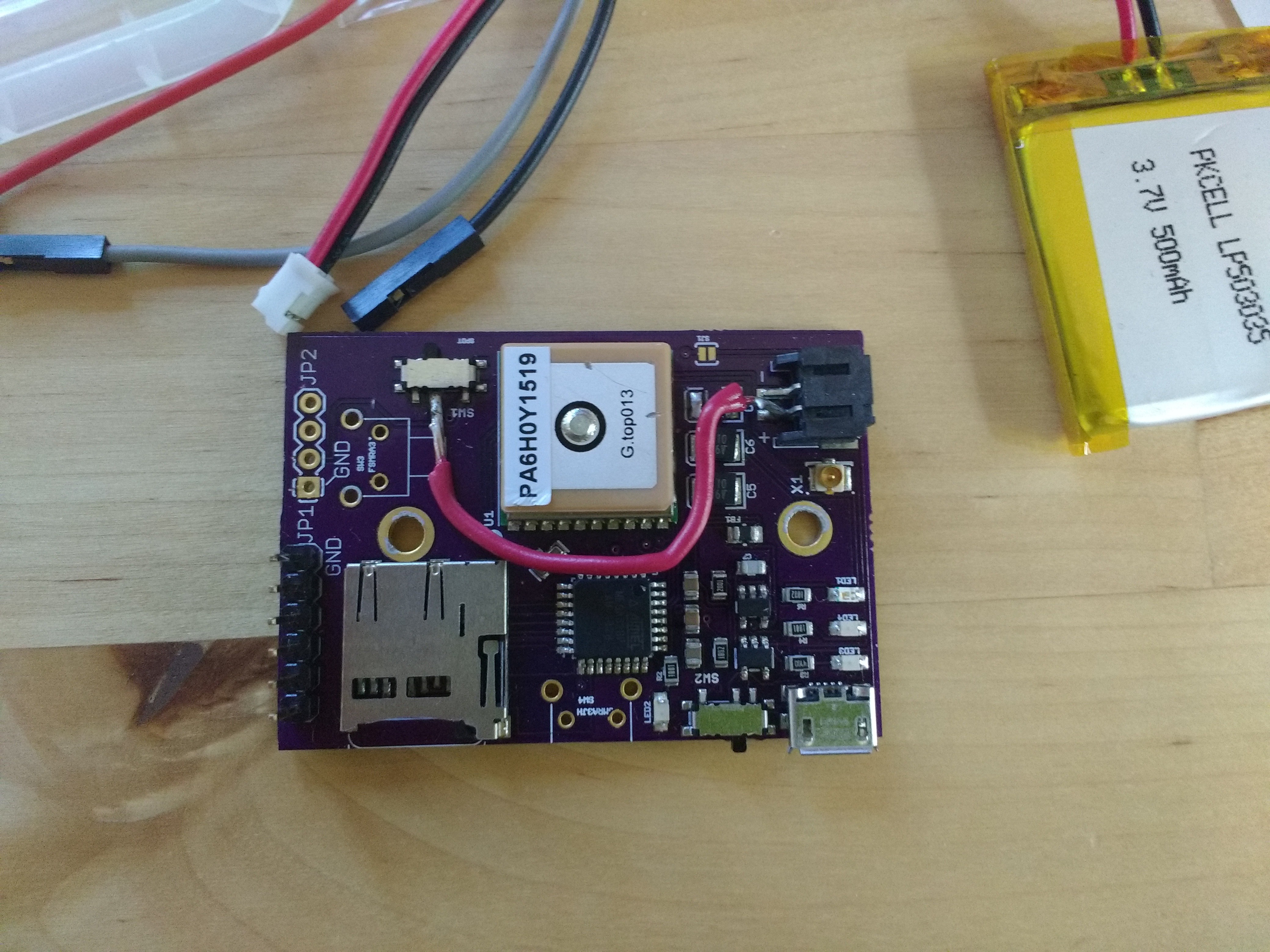
Discussions
Become a Hackaday.io Member
Create an account to leave a comment. Already have an account? Log In.