Antti Lukats
-
Blinky, all the blinky!
09/20/2015 at 19:16 • 0 comments[christoph] I seem to love making blinky examples. My latest series of git commits cover the blinky basics, such as
- using open drain outputs for an LED with current limiting resistor,
- the built-in constant current LED driver (no resistor required),
- low-frequency oscillator (10 kHz) and
- high-frequency oscillator;
- dividing clocks down to something useful (visible)
-
SPI Flash writer from Rasperri Pi
09/20/2015 at 16:58 • 1 commentWhile Lattice Diamond Programmer or DIPSY SPI Tool can be used on PC to write spi flash, Hackaday project #SPI Flasher May also offer direct SPI flash writing from Rasperri Pi
Thanks Yann!
-
DIPSY standalone SPI Flash Boot
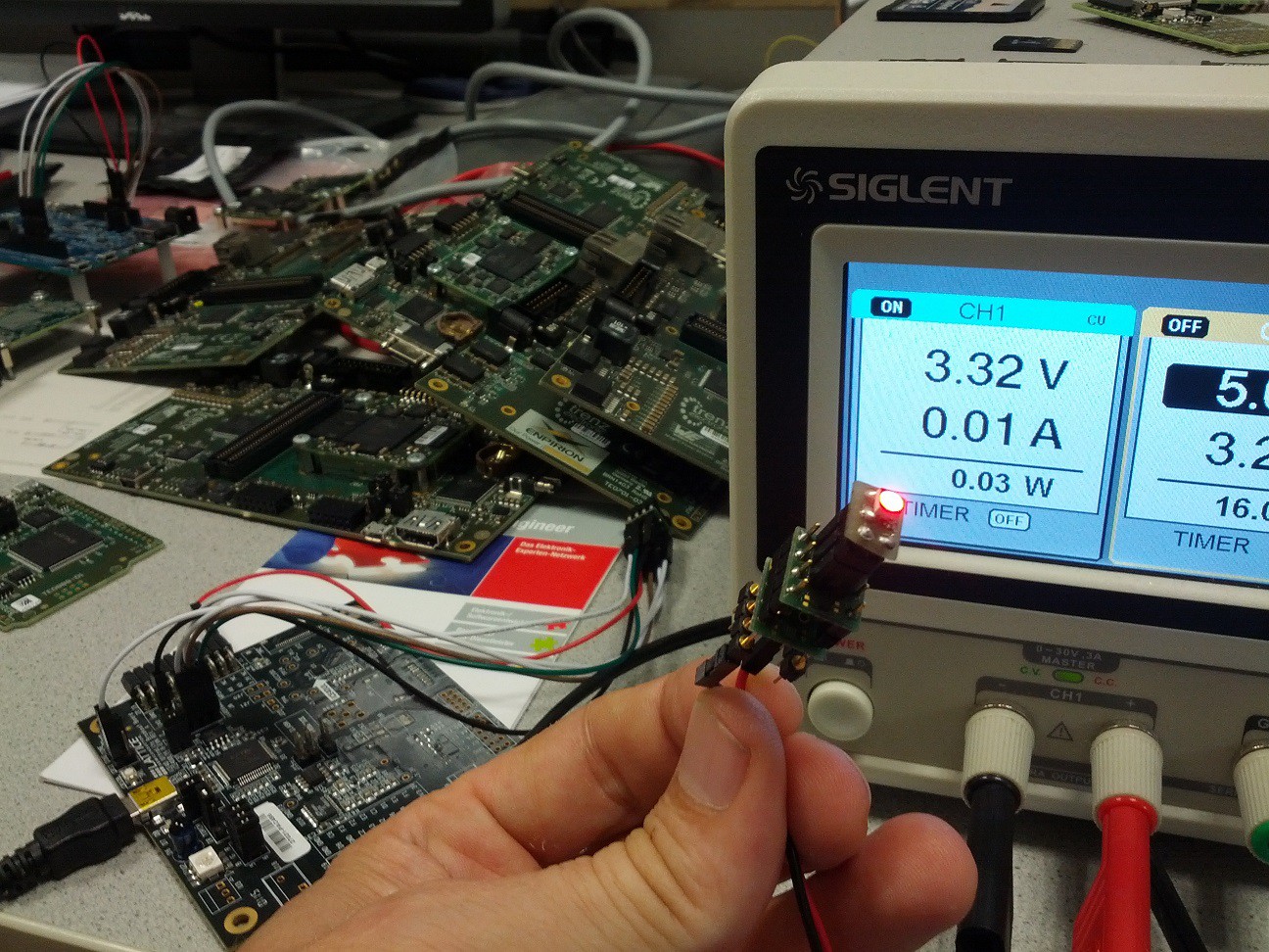
09/19/2015 at 19:10 • 1 commentI found some very old AT45DB161E SO8 and made "flash adapter" for the DIPSY-EasyPCB to test standalone boot from flash. Lattice Diamond did have this device in the Flash selection list, but was not able to write the flash.
So I did give a try to DIPSY SPI Tool what I did finish a few hours later - there was from old times some SPI functions included.
To my big surprise DIPSY SPI Tool, well it did write the flash, and voila:
![]()
-
WS2812B driver
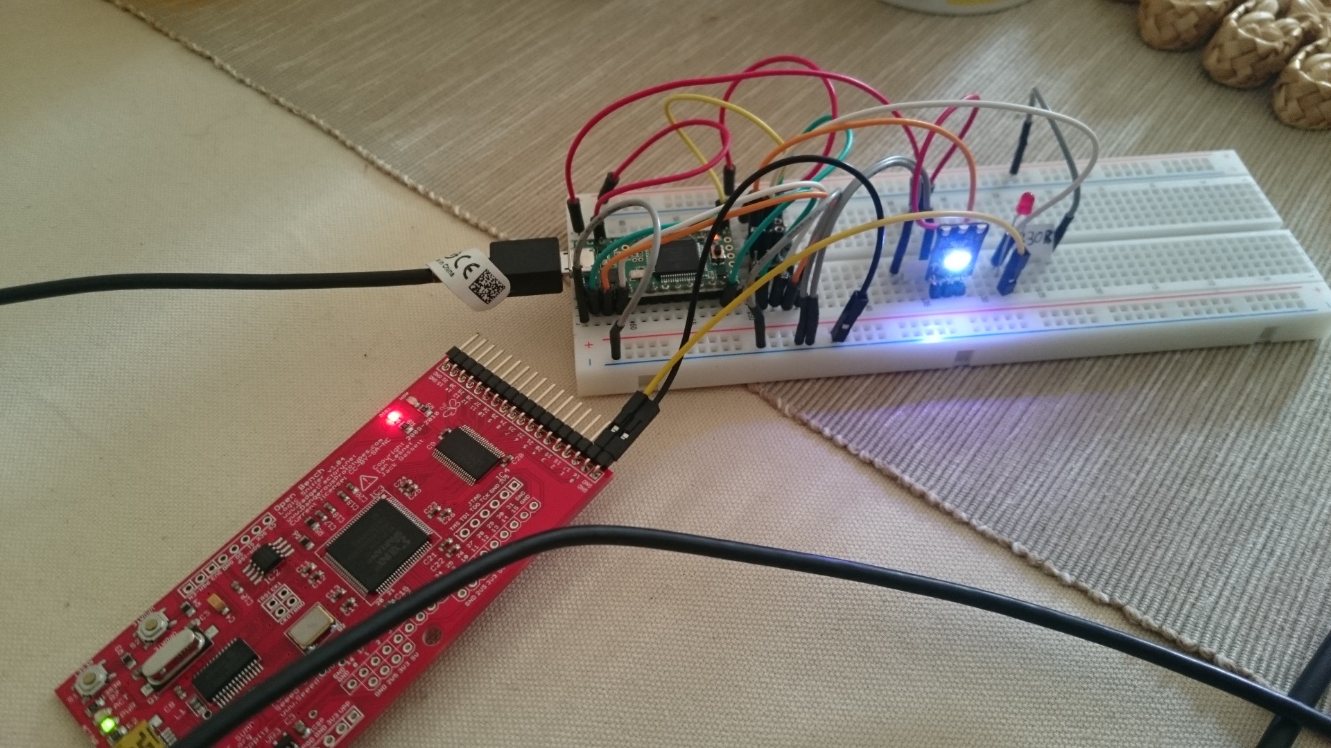
09/18/2015 at 21:14 • 2 commentsdipsy has lots more resources than necessary for creating a WS2812B driver. On our way to a really useful implementation I created the actual driver core that converts 24 bits to the correctly timed pulse train and tested it with a single "pixel":
![]()
After hours of troubleshooting I decided to connect my logic analyzer - only to find out that I had connected the WS to the wrong pin. Well, that's life.
I also created a "cycling" example that cycles through red, green, blue and white over and over again. Both can be found in my git fork (/THP2015/examples/verilog/ws2812b_standalone), soo to be pulled into antti's repository.
The goal is to create a WS driver chip with a frame buffer and SPI interface. The dipsy FPGA has 14 RAM tiles with 512 bytes each, so we can easily drive a total of 2048 pixels (using 12 tiles: 4x512, 3 bytes for each pixel) with this thing.
This blog post was very helpful in understanding the timing: https://cpldcpu.wordpress.com/2014/01/14/light_ws2812-library-v2-0-part-i-understanding-the-ws2812/
-
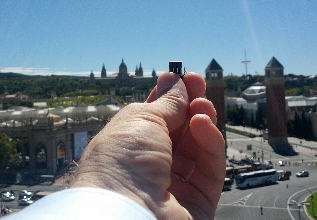
CHURCH and ICON
09/18/2015 at 19:50 • 1 commentIt all depends on your view angle:
![]()
DIPSY in Barcelona!
![]()
And this is the ICON to be used in for DIPSY :)
-
How to use the LED driver pins as user I/O
09/17/2015 at 08:39 • 4 commentsThe dipsy FPGA is intended to be used as an LED driver chip, but we can also use the LED pins (RGB0..2, IRLED and BARCODE) as user I/O. To do so, special driver IP needs to be used. Here's a simple verilog source to demonstrate this:
module top (
  input pin_in,
  output pin_out
);

wire mywire;

SB_IO_OD #(
  .PIN_TYPE(6'b000001),
  .NEG_TRIGGER(1'b0)
) pin_in_driver (
  .PACKAGEPIN(pin_in),
  .DIN0(mywire)
);

SB_IO_OD #(
  .PIN_TYPE(6'b011001),
  .NEG_TRIGGER(1'b0)
) pin_out_driver (
  .PACKAGEPIN(pin_out),
  .DOUT0(mywire)
);

endmodule
There an input (pin_in), an output (pin_out) and a wire that's just used as an internal signal. This is as simple as it gets, and when I first tried this I just wroteassign pin_out = pin_in;
But iCECube barfed at that, telling me that this couldn't be realized with LED driver pins. So I asked antti for advice and he pointed me at those SB_IO_OD things. They are described in the "iCE40 LED Driver Usage Guide". Let's have a closer look at the first one:SB_IO_OD #( // IP name .PIN_TYPE(6'b000001), // configure as simple input, no output capabilities .NEG_TRIGGER(1'b0) // don't know what that means exactly ) pin_in_driver ( // the instance name .PACKAGEPIN(pin_in), // the pin to use as input .DIN0(mywire) // where to put data from that pin );
There are more ports to this IP which can be used to synchronize it to a clock, but we don't need that.The output is very similar:
SB_IO_OD #(
  .PIN_TYPE(6'b011001), // configure as simple input pin
  .NEG_TRIGGER(1'b0)
) pin_out_driver (
  .PACKAGEPIN(pin_out), // connect to output pin
  .DOUT0(mywire)        // with data from this wire
);
I hope this helps those who try to use LED driver pins as simple I/O. I was able to apply a 1 Hz square wave on pin_in (RGB0), and drive an LED (with a current limiting resistor) on pin_out (RGB1).This example is currently in my own dipsy fork (THP2015/examples/verilog/basics/01_inout/), but I've already created a pull request for antti.
-
DIPSY flying to Lattice !
09/16/2015 at 08:06 • 2 commentsTwo set of DIPSY + DIPSY EPT are on the way to Lattice I have received samples and free eval boards from Lattice, now there is something I can give back!
DIPSY so COOL with ICE COOL PFGA on it
-
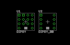
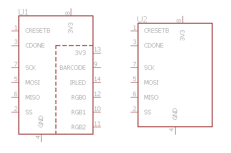
Eagle library
09/12/2015 at 15:43 • 0 commentsCreated an eagle library with two simple dipsy schematic symbols and footprints:
- one full version with all 14 pins,
- one breadboarding-like version with the 8 outer pins.
I couldn't really test it (yet), but I think it's ok as it is.
![]()
![]()
Find the library in the dipsy main github repo
-
Gotcha: Simulation startup
09/12/2015 at 14:42 • 4 commentsIt's very cool that xilinx give us free software (Vivado) that we can use to simulate our designs. BUT there are some gotchas. When I tried to simulate writing to/reading from RAM it seemed that nothing worked as intended, until I simulated for a longer time (> 100 ns). After skimming the datasheets, RAM usage guides, I finally opened the "Vivado Design Suite User Guide", where I found this:
"Apply stimulus data after 100ns to account for the default Global Set/Reset (GSR) pulse used in functional and timing-based simulation."
This boils down to: RTFM. Ah well...
-
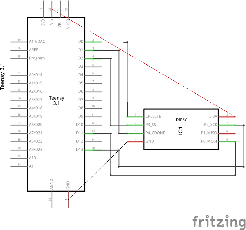
FRITZING!
09/12/2015 at 09:59 • 2 commentsMany years have passed since I last looked at Fritzing. Nice to see many improvements. Its is really a breeze to make simple stuff. Really.
![]()
This is all you need to load a DIPSY hardware "BITSTREAM" a 30KByte binary file using TEENSY.
Amazing, and it is instantly documented the hardware setup.
![]()
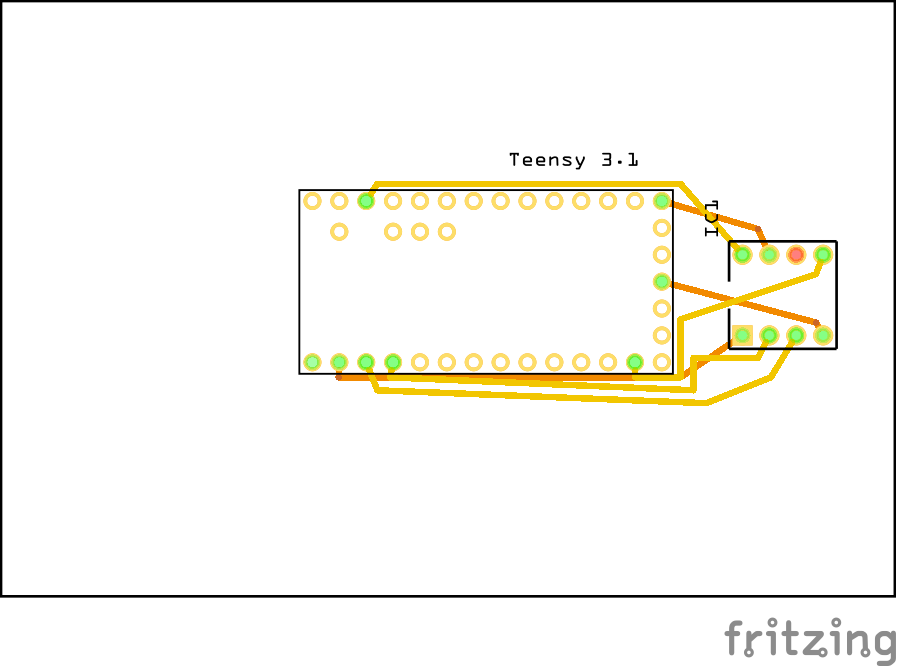
And you have schematic too!
![]()
And autorouted PCB also.
And there is no need to use screen capture, all views can be saved to bitmap files.