 Martin Vincent Bloedorn
DeltaWalker has a fairly simple mechanical design, and even though the pictures do most of the talking, I'll take briefly lay out some of its aspects.
Legs and coordinate systems
The legs themselves were designed to be as simples as possible:
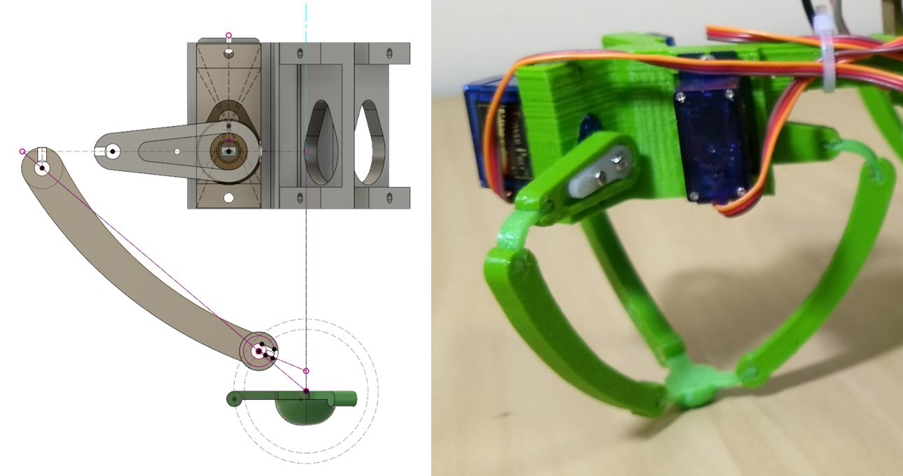
Three SG90 9g servo are mounted 120 degrees apart. On each leg, there are three... "Leglets", shall we say. On each, a small 3D printed hinge - the femur - is attached via the servo horn to each, and the tibia connects to the femur via a flex joint. Since I'd go crazy trying to fit tiny bearings into 12 tiny joints, I think this flex joint is probably the most interesting thing in this whole setup. Getting the correct size and thickness for the joints was trial and error, but it actually took me two prints to settle with this design (so there's certainly room for improvement).
The foot is also a flex, 3D printed part. There is still a lot of slippage when the DeltaWalker walks around: the foot is too low, so the plastic of the tibia ends up rubbing against the grund. This design will probably be changed in the near future.
Like I've mentioned earlier, I stole all the kinematics know-how from this glorious post in the Trossen Robotics forum. In that post, a few reference images are supplied (outlining parameters that are later referenced in code). Below is the one outlining the leg's coordinate frames used in the IK computation, a parameter names (conventions that I also adopted):
To further follow the convention, the servos are considered centered (i.e., angle = 0) when the tibia is parallel to the XY plane. Positive angles move the tibia's tip in the -Z direction.
Body and more coordinate systems
The whole body was designed to be printable as a single part:
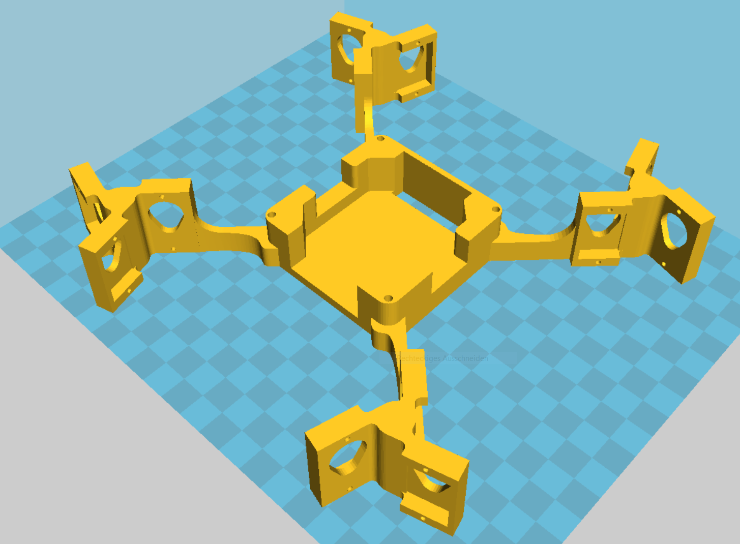
There are some supports required for each servo attachment, but they're tiny and fairly easy to remove. Assembly is also straightforward as it seems. Just note: legs 0 and 1 are mirrored in relation to legs 2 and 3, so you'll have to mount six leglets with the femur facing one side, and another six in mirror image.
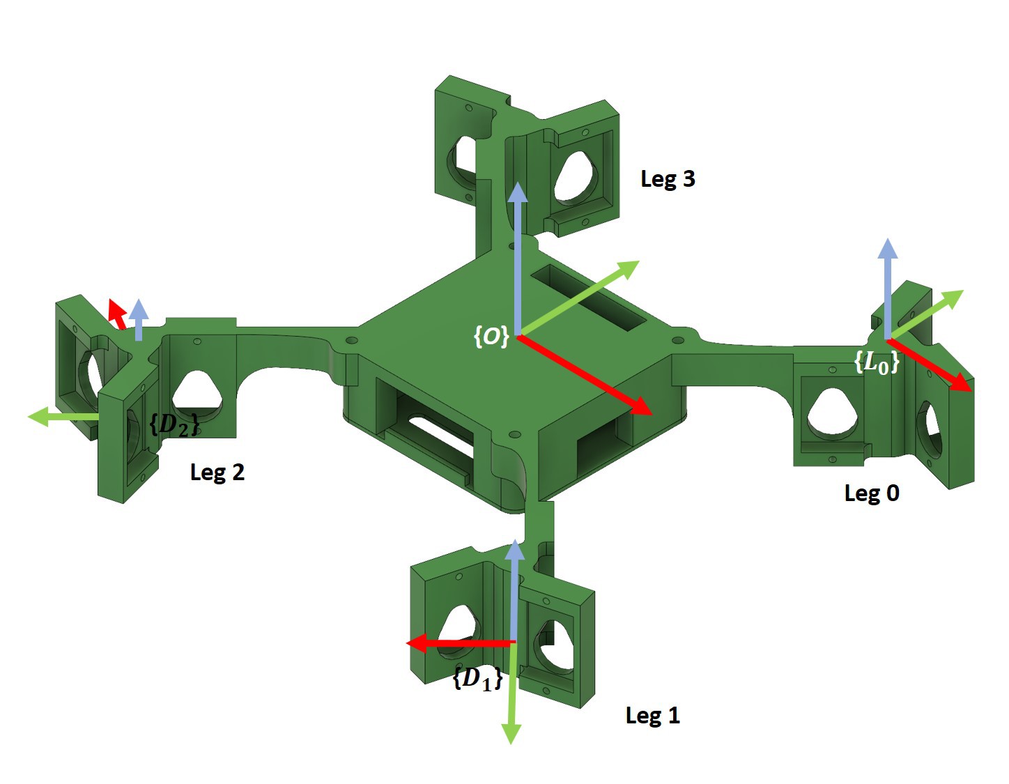
As a quadruped/hexapod/walker-robot newbie, I wanted to avoid going crazy with those 12 servos, so I quickly adopted a few numbering conventions, and defined some standardized coordinate frames to make my life a tad easier:
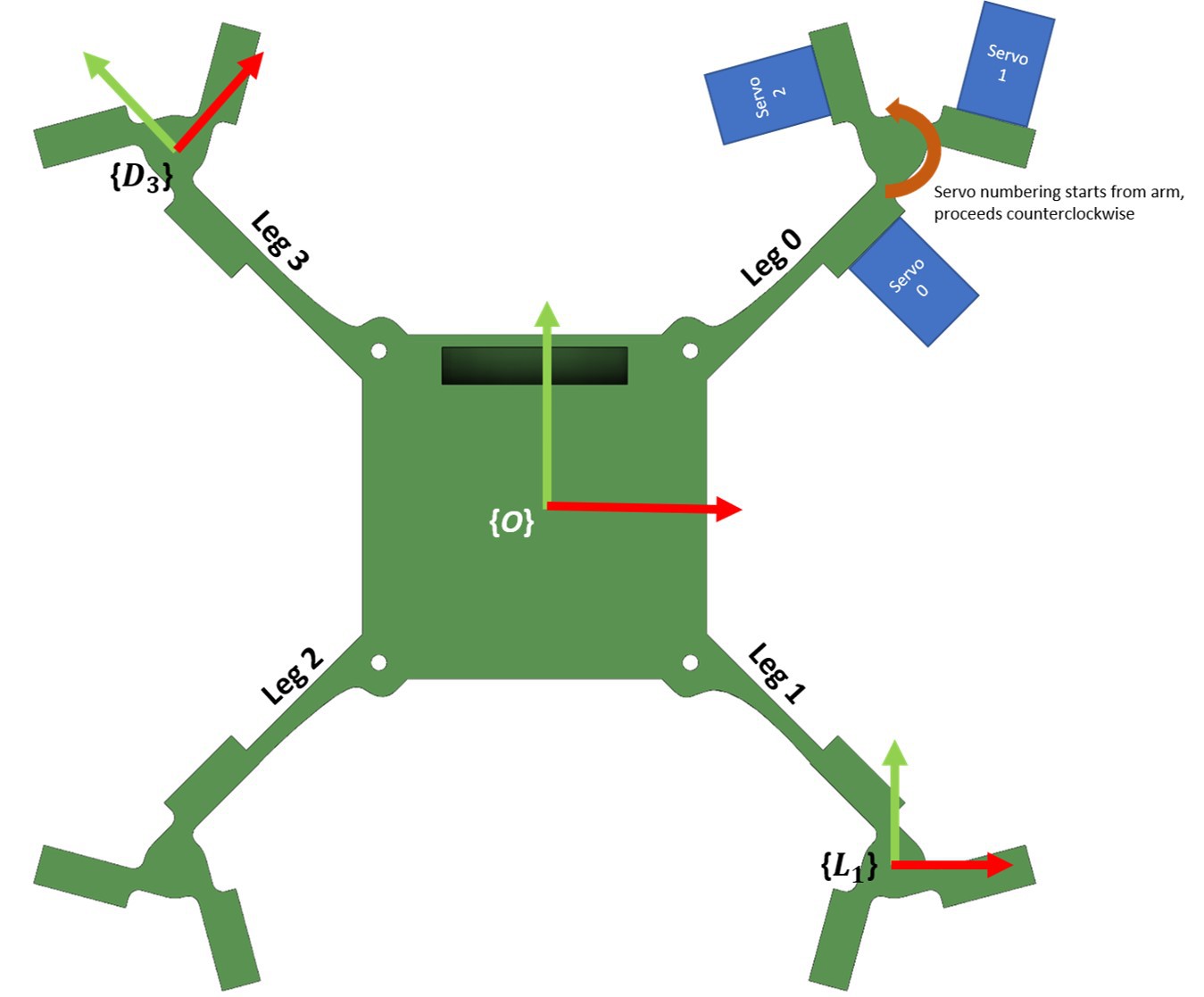
- The origin {O} is placed in the body's center; +Y facing "forwards" (arbitrary).
- Servos are numbered from 0 to 2 on each leg, starting from the arm, going counterclockwise.
- Legs are numbered clockwise, starting from the +X+Y. I actually wanted them to follow the quadrant numbering convention, but apparently I got those reversed *facepalm*. Too late to change it up though.
- Each leg has a L_n coordinate system that is used by the firmware to specify the feet's positions during gait.
- Each leg has a D_n coordinate system for IK computation, where Y+ is aligned with the corresponding leg's support arm (following the conventions from my IK reference). There's a Z offset a rotation between any L_n and D_n pairs, see below:
Why so... many coordinate systems
After I defined all these CS, it bacame really easy to manipulate the robot and do transformations with it (i.e., translations or rotations). Translations are particularly simple:
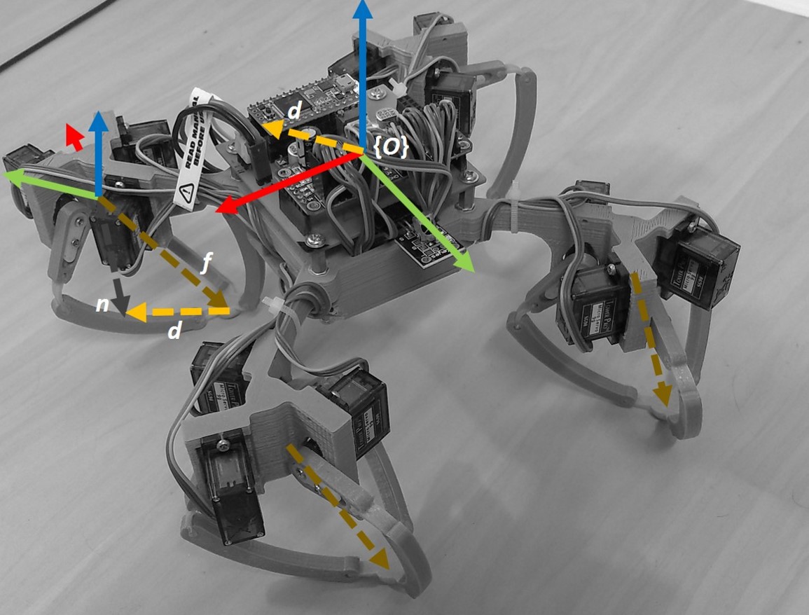
For any desired bodily translation given by a vector d, each leg's foot has to be set to a position f = n - d, where n is the foot's position when the leg is "resting", i.e., all servos are centered.
Yeah. That's it. Quick, painless and marginally useful :)
Discussions
Become a Hackaday.io Member
Create an account to leave a comment. Already have an account? Log In.