 robheffo
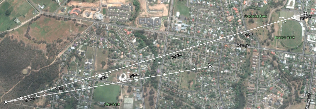
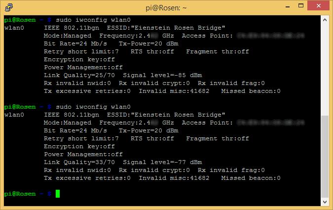
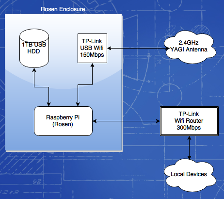
I have build two Raspberry Pi based boxes that connect to each other via WiFi on Channel 1 (2.4GHz) since no other WiFI AP in the area is using that channel, so I get a nice high-speed uncongested link.
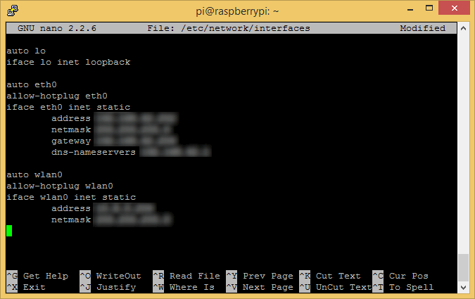
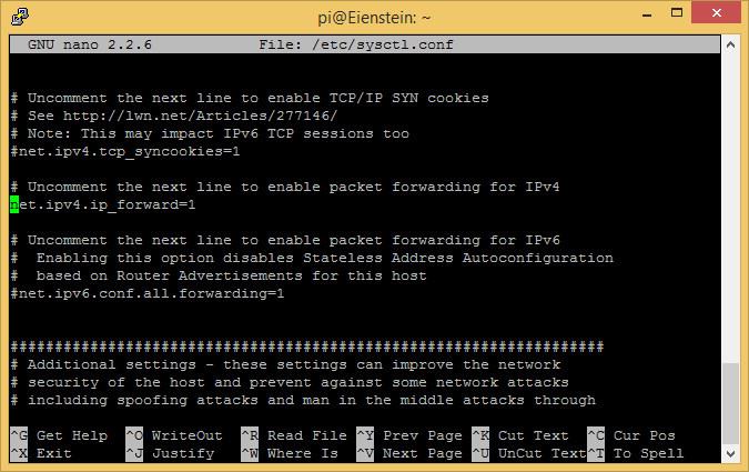
The WiFI dongle on my end is in AP mode, serving up the SSID for the bridge. The other box connects to this and connects to an OpenVPN server running on the Pi 2. The WiFi is firewalled on both ends so that the only traffic allowed on the link is the OpenVPN traffic and ICMP packets for testing the endpoints are responding.
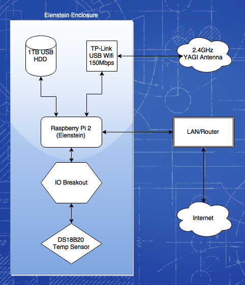
I included a 1TB USB hard disk in each box with the root Raspbian filesystem on the USB drive in order to save the SD Cards from wear and tear. It also gives plenty of room for implementing at a later stage transparent HTTP(S) proxying & caching. I am looking at implementing a local cache for other frequently accessed media in order to reduce the load across the bridge also.
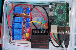
I picked up a couple of 5V 15W switchmode power supplies from ebay to handle powering the Pi and WiFi dongle which being a cheap unit didn't exactly have the smoothest output. I whipped up a couple of filter boards with an inductor and a handful of capacitors of various sizes on some Veroboard to get the ripple under control.
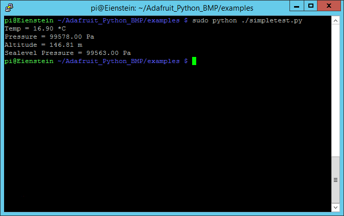
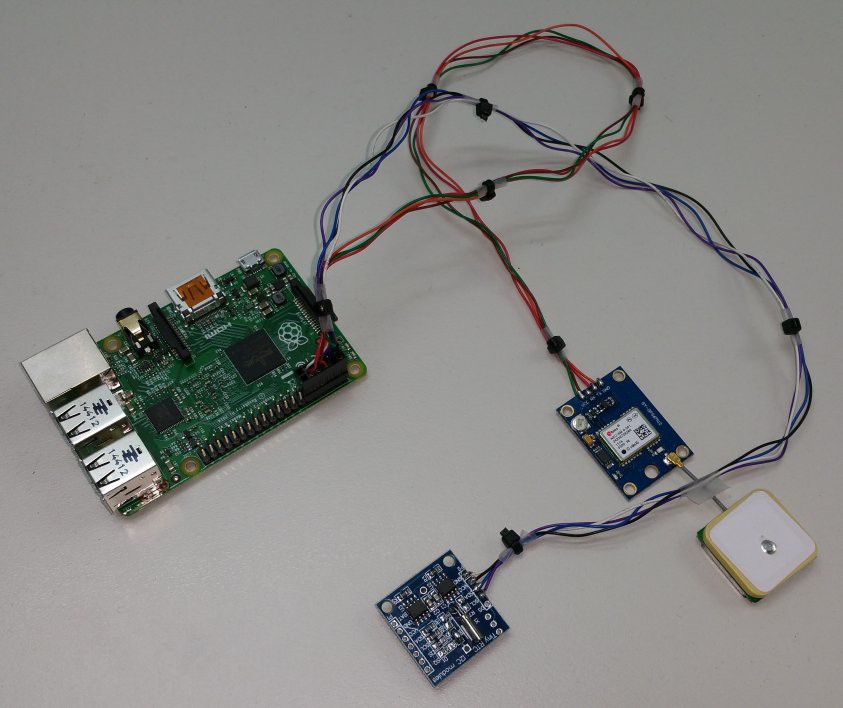
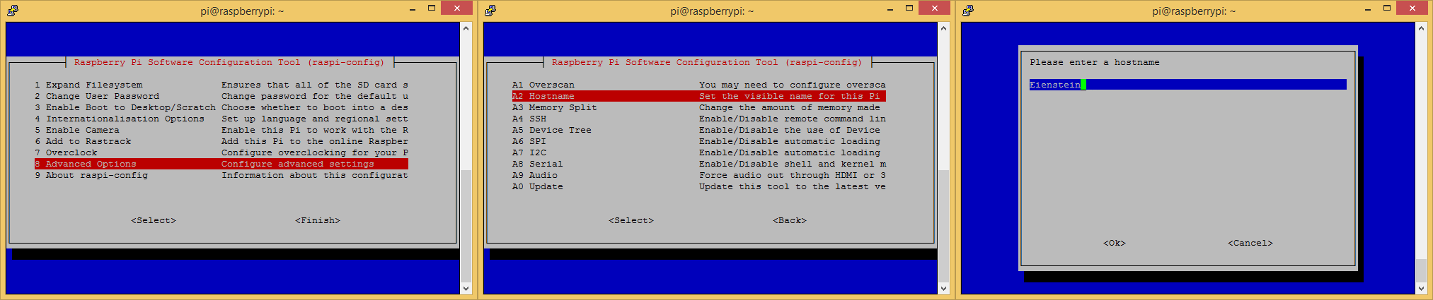
I also created a breakout for the GPIO header on the Pi 2 so I could add a Dallas 1-Wire temperature sensor (CrystalFontz have some really nice temperature sensors based on the DS18B20 digital sensor for the CFA-6xx Series) for monitoring the environment inside the enclosure.
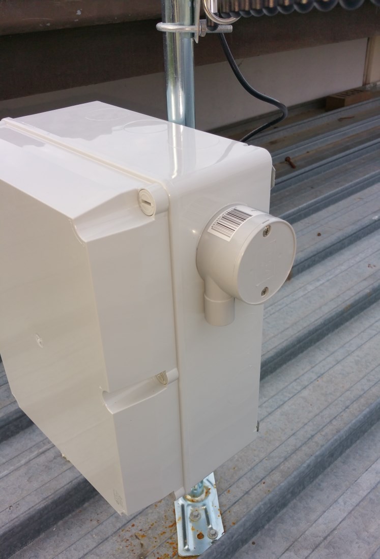
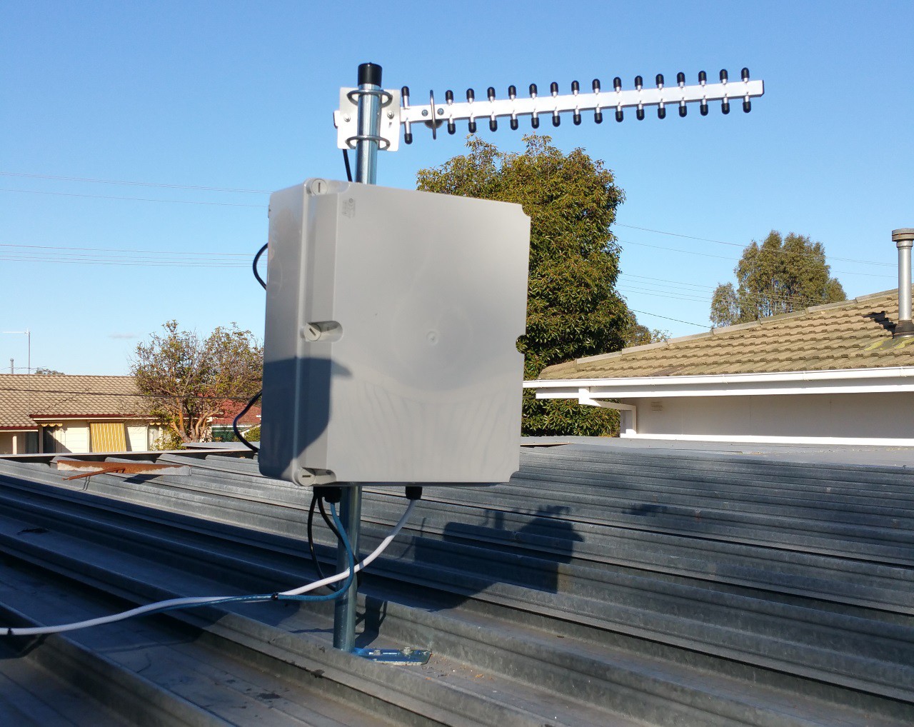
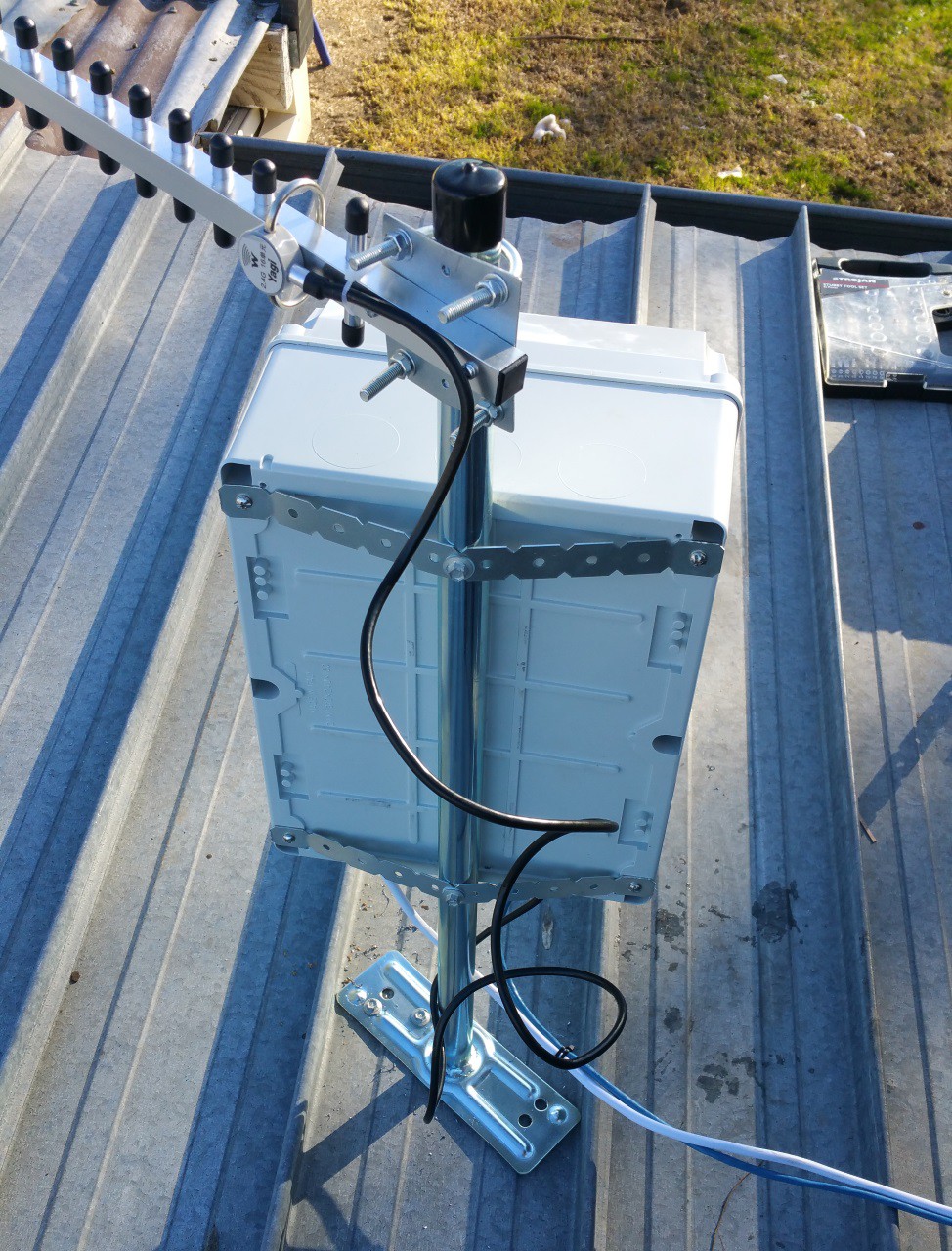
I sourced some weatherproof ABS boxes from an electrician friend who I do some work for on the side from time to time which I have mounted all the equipment in, It's laid out nicely if not a bit cramped. The boxes will be mounted on the TV antenna mast along with the 2.4GHz Yagi antenna to keep the cable length as short as possible.
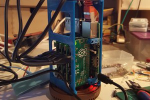
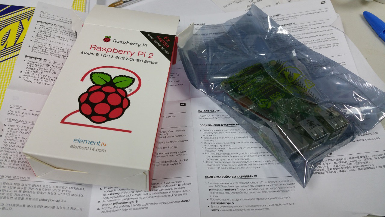 So, finally after almost a whole day of waiting and two trips to the Post Office, I have my new Pi 2. I got an email from Australia Post saying my package had been delivered. No one around the office had seen it. I dashed home during my lunch break to see if it had been delivered there (alas, it had not) and to meet up with my Electrician friend who is installing power & ethernet under the eaves to show him the Job.

 blinkingthing
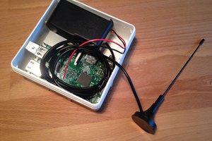
 davedarko
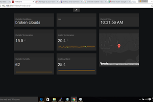
 Brenda Armour
http://www.hackaday.com/2005/06/13/ronja-optical-data-link/
Ah! Look where I found it. Probably!
The
design originates from 2001 so it's well-tested, thought to be between
1,000 - 2,000 setups using it in the world. So it's not gonna be too
hairy. Especially with the short distance it has to work in your case.