 zaphod
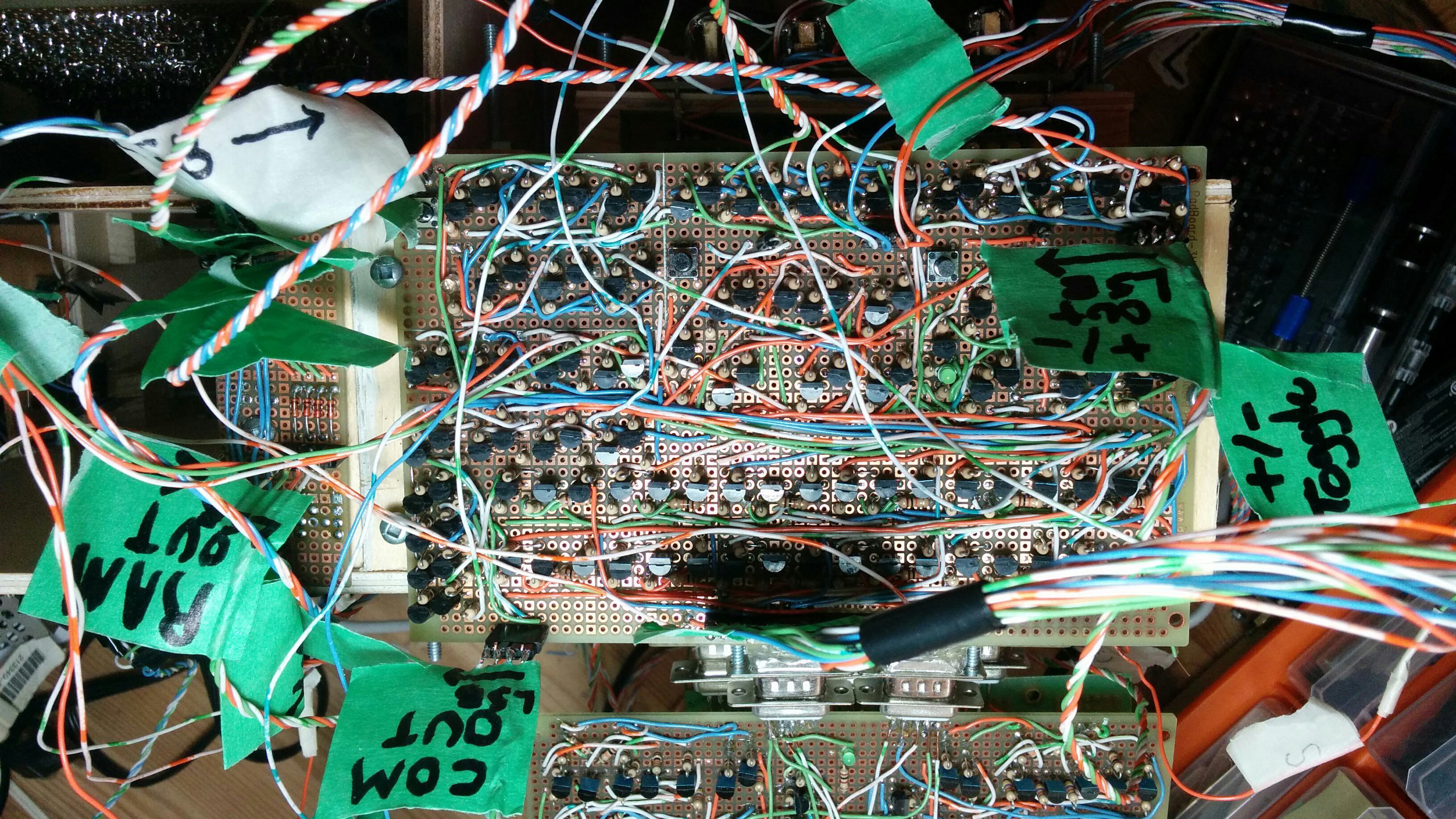
I have successfully tested and rearranged all of the modules that make up the processor and on their own each module seems to be functioning. I have also built a new board:
this board is essentially just control logic it takes decoded instructions in on a 10-bit instruction bus and then turns them into usable load/output enable signals. its mostly just AND gates that AND the instruction and load clk to produce an appropriately timed load/out put enable bit. if you look at the new architecture diagram:
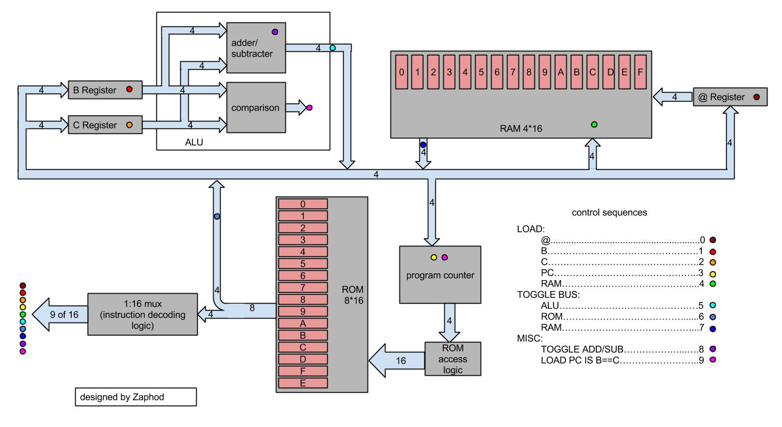
you'll notice that there are only three places data on the main bus can come from: RAM OUT, ALU OUT, and ROM OUT. to decide which location data is coming from the computer needs output enables, i.e. if you want to load the @ register with a value from ROM the ROM OUT bus must be enabled and the ALU OUT and RAM OUT buses must be disabled. to do this i built a 'bus toggle' circuit:
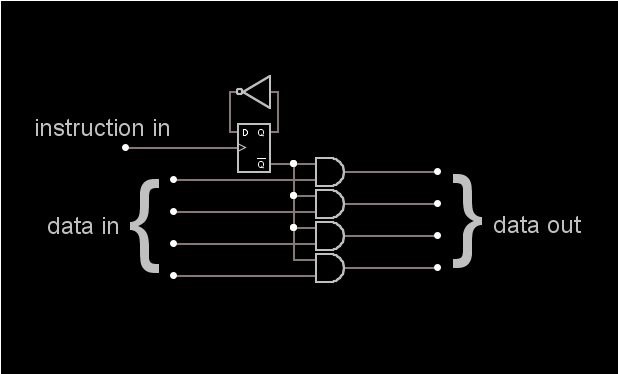
basically whenever the the above logic receives a 'toggle' command it switches to the opposite of what it was previously, i.e. data is being passed through>toggle>data is not being passed through or vice versa. this allows the programmer to decide where the data on the main bus is coming from by means of toggling the appropriate sources. a side effect of this is that a careless programmer can accidentally superimpose data from two sources onto the main bus at the same time. I actually only built two of the above circuit, one for ROM OUT and one for ALU OUT, the third I implemented in software on the arduino. while this is technically cheating, I don't feel it takes away from the project because, a) i have demonstrated that I can build the required circuit, and b) it is not technically part of the processor, as it is RAM access logic.
after building the control logic board I proceeded to assemble the computer and attempt to run the very first program, it failed.
as you would expect I was thoroughly disappointed that the computer did not work, I wasn't realy expecting to work on the first try, but still... any way I spent a lot of time retesting all of the modules in various configurations and discovered a few things:
1. each module works as expected if it receives 'good' signals (i.e. data one = v+ and data zero = v-)
2. the ALU works as expected
3. the program counter ROM and ROM access logic all work together as intended, including loops, if they receive 'good' signals
4. the register work if given 'good' signals
5. the RAM works if given 'good' signals
6. when all the pieces are assembled things stop working
this was pretty mystifying. each piece of the processor seems to work on its own but when I put them all together they seize up and stop working, the RAM refuses to load, the register store data incorrectly, and the program counter resets incorrectly. at present the best explanation I have for this behaviour is that data sources (ROM, ALU, (maybe RAM)) are not giving 'good' signals. the problem with this is that I don't really know what constitutes a 'good' signal. this is because I don't know what the logic levels are/should be for RTL. because of this I only know what 'perfect' signals are i.e. connect inputs directly to positive or directly to negative. when I measure the logic levels of the data on the main bus I can see that it is not perfect, (i.e HIGH != 5v and LOW != 0v) however I don't know how to fix this using transistors. if anyone has any ideas feel free to comment.
this problem is really bugging me because obviously some one figured out how to solve it because digital logic works, but how that was done I don't know. so far I've come up with two potential solutions for restoring logic levels to 'perfect' levels
1. relays. relays are switches so I could theoretically use them to switch rail voltages directly. the problem with relays is that they take lots of power to switch and I'm not sure if the fuzzy values coming out of my logic would be able to flip them
2. comparators. I've already used comparators on the project, but it was technically not in the processor, it was in the ROM access logic (cop-out, I know) I am fairly sure that using comparators would restore logic levels to working values but I am hesitant to use them because I don't fully understand how they work and as such would be forced to use a chip.
Ideally what I'd like to do is build a discrete circuit that is equivalent to an lm339, but I have no idea how complicated a thing to do that would be, and at this point I just really want to finish this project.
so in conclusion: I'm stuck because I don't know enough about electronics and the only way out seems to be the use of integrated circuits which kind of defeats the purpose of the project. if anyone has ideas (or a really good justification for using ICs) please comment.
Discussions
Become a Hackaday.io Member
Create an account to leave a comment. Already have an account? Log In.
This is a problem I have run into as well. So far my best results have come from using open collector outputs for everything, and being careful with how I put things together. Even then I frequently find voltage drops that end up requiring some form of re-work to eliminate.
I will also point out that circuit simulator frequently indicates a voltage drop that does not exist when I assemble the circuits. This has caused me no shortage of grief working on registers.
One of my original considerations, which I do not think I have written up yet, was whether or not to use some kind of FET instead of BJTs for the transistors. The reason being that FETs are voltage driven instead of current driven, which has quite a bit of impact on how things work. At present though, I'm still using BJTs because I have not found suitable FETs, and because I have not had any time to work on that project for several months, so that discussion is still theoretical for me.
What I have noticed is that BJTs can be quite finicky. My suggestion would be to starting connecting modules one at a time and watch what happens to the driving signal.
Are you sure? yes | no