 Peter Wasilewski
Hi!
Wow It’s been a while since last update apparently we've forgotten about Hackaday, but not about motee ;) A lot happened during this time and I’d like to tell you about it. I think I’ll divide it into a few logs so it’ll be easier to read.
CHANGES
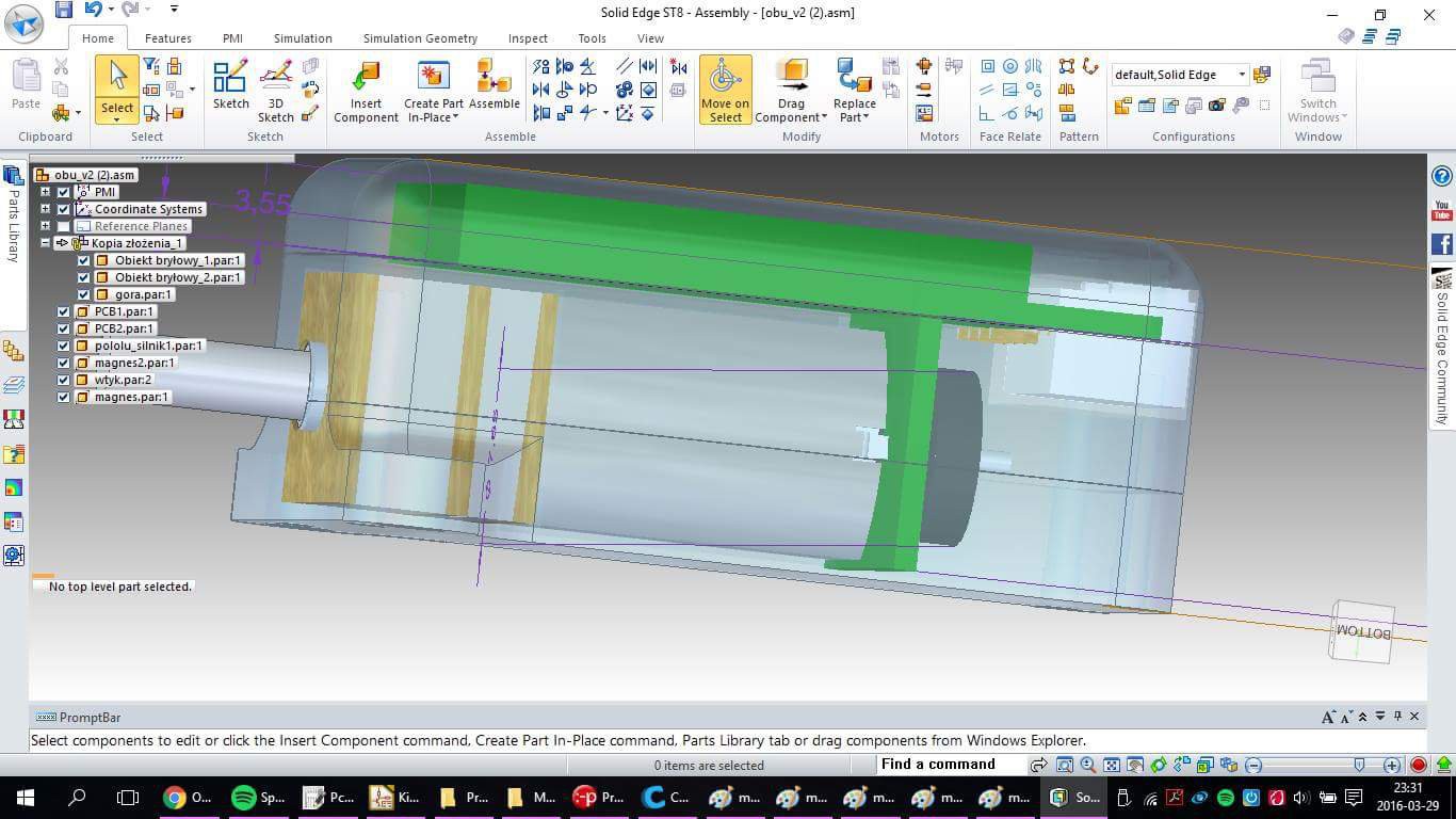
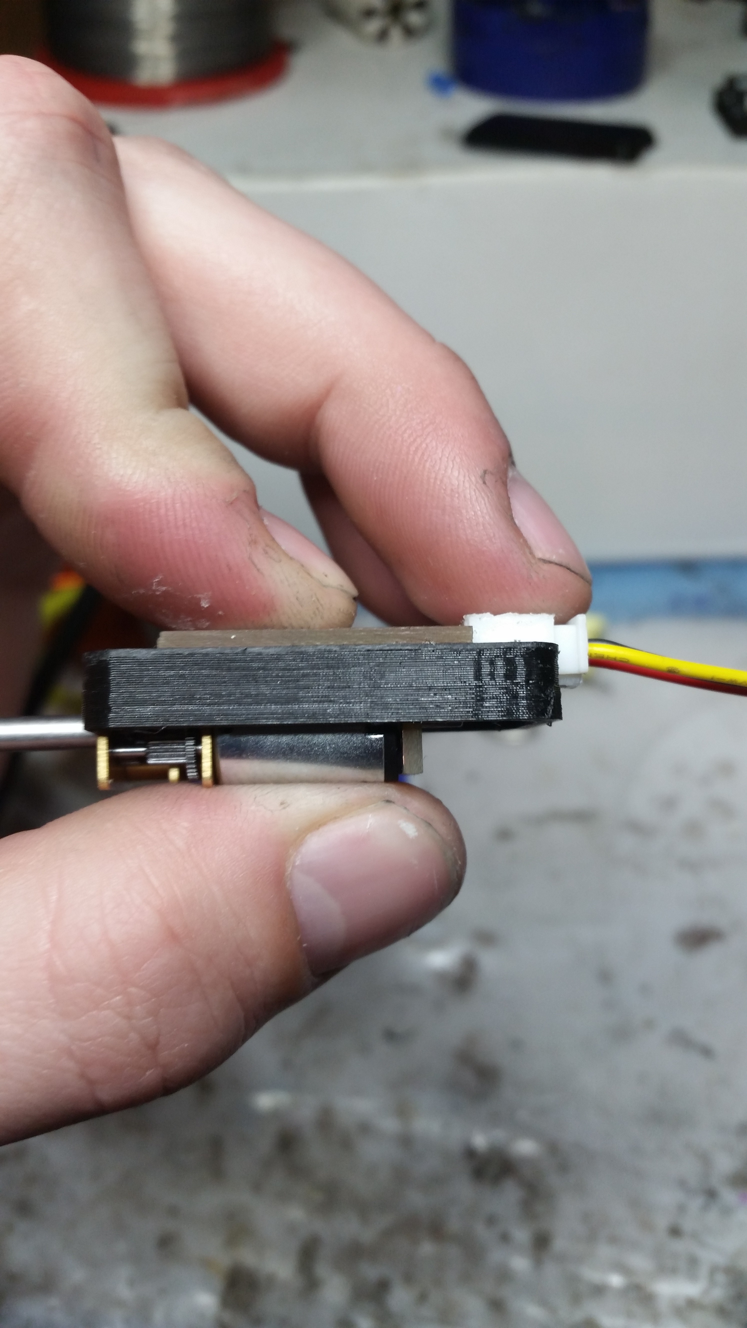
We’ve done two or three prototypes, but they are a lot different from the ones from last log. They have a built in microcontroller, encoder and communicate through rs485. These are the main differences from the first version. It sometimes had problems with i2c communication due to electromagnetic interference from the motor, so out priority was to change the way of “talking” to the module. Besides, the motor is fully integrated into the case, so users don’t have to worry about breaking something. The case itself has two or four mounting holes, so it’s much easier to adapt.
SOFTWARE CHALLENGE
Our software goal is to make mote compatible with Arduino. Latest PCB has a microusb connector, and we managed to run a special bootloader for STM32 ( thanks to STM32Duino), so now we are able to program Motee in Arduino environment without any external programmers. We believe that will make Motee much more attractive.
RS 485 COMMUNICATION
The communication is based on an evaluation board like Arduino or RPI being a master, and motors connected in parallel. Another option is to make one of the motors the master and others the slaves. That’s the biggest advantage of built in microcontroller – we don’t have to use other boards as masters to control the motors.
LAST PROTOTYPE
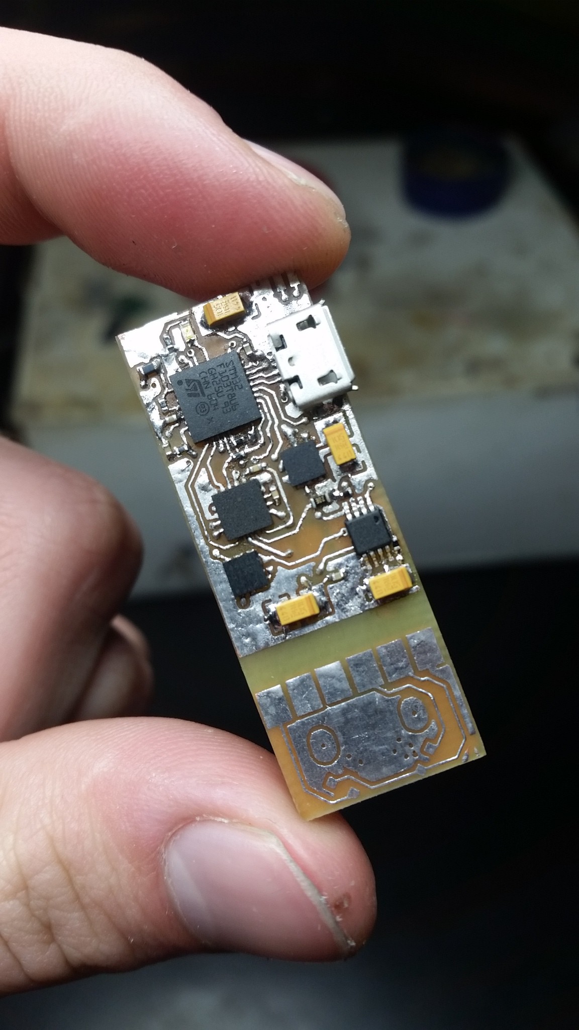
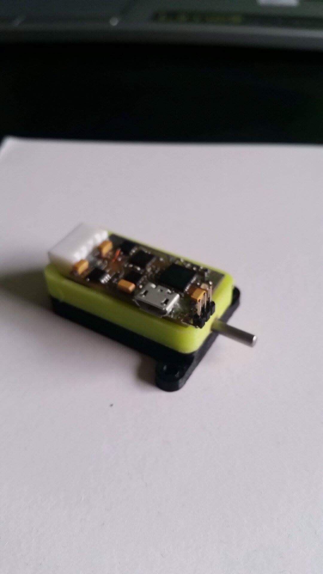
As I mentioned earlier it is ( in contrast to previous models ) based on STM32 microcontroller. We decided to choose one of ST’s family because it has a hardware encoder support, higher clock frequency, and many more peripherals. Below you can see a full list of main components :
-STM32f103 microcontroller
-Rs485 controller
-Hall effect encoder
-H bridge
-Two LDO regulators
- USB connector and universal 4 pin output connector
For now the pcb has many bugs, and that’s our work for next weeks. Make a nice pcb and fix all the issues we had to deal with this version.
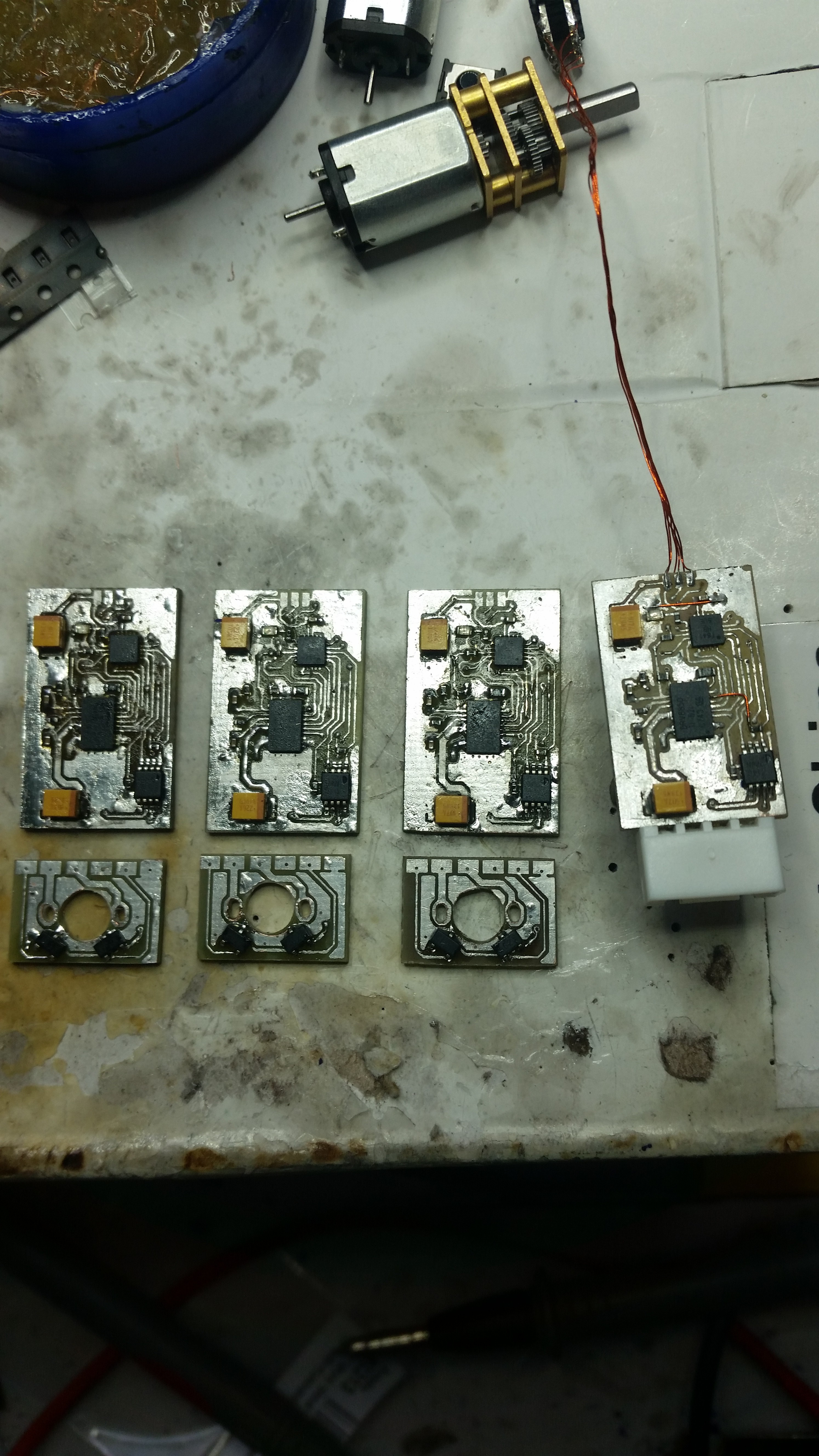
Below you are able to see some photos from the prototyping process ;)
STM32 prototype
AVR prototypes :
Peter.
Discussions
Become a Hackaday.io Member
Create an account to leave a comment. Already have an account? Log In.