 Bob Baddeley
PCBs arrived this week from china (I use http://smart-prototyping.com for my cheap PCBs). I was able to get all the PCBs I need for the full project (I needed 60) for $25 + $20 shipping, so under $1 per PCB. Not bad for prototyping! At that price, it made sense for me to just order the full number and hope they worked on the first try instead of ordering a couple and then ordering a second batch. Anyway, they arrived, so I spent the day doing some hardware validation.
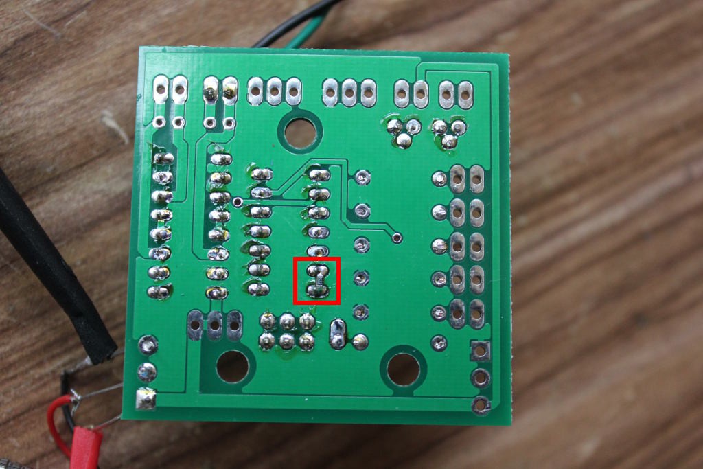
To me, validation means slowly hooking up each part of the circuit and testing it. In this case, I also wrote an arduino sketch that focused on each specific section. Unfortunately, after my day of testing I had 2 errors. Fortunately, one of the errors was solved by putting a SMT resistor in between two adjacent .1" pins (pro tip 0603 resistors fit perfectly between .1" pads), and the other error was my servos had a different pinout than I expected, but I was able to swap the servo pins in the connector and the problem was solved. So no rework necessary, and no need to do a new board revision. Woo!
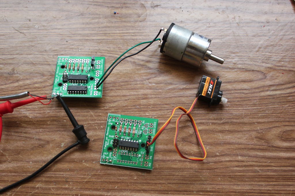
Here's what the new PCB looks like:
A quick walkthrough of the schematic:
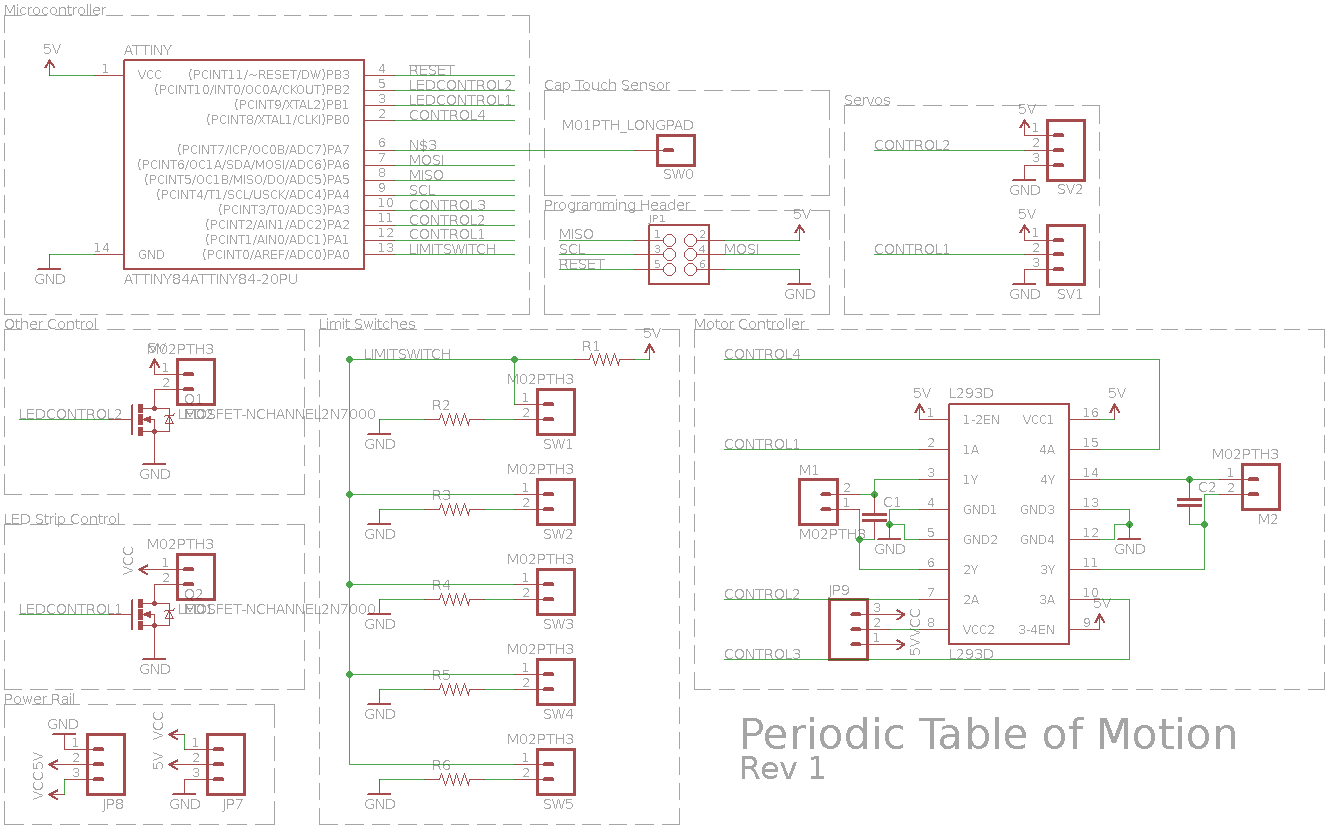
First there's the microcontroller. An ATTINY44A-PU. Next is the cap touch sensor, which is just a pin. This was the mistake I made. There should also be a large (>1M) resistor between pins 6 and 7, which isn't captured on the schematic. Oops. Next is the programming header. There are two servos as well. For some reason the servos I ended up with had the control and +5 swapped. Not a big deal. Next we have "other control" which switches a +5V load. It can be used for whatever. There's also an LED Strip control, which is used to indicate when the cell is on. The Power Rail connectors are for attaching the power bus, and there are two for convenience. Only one is necessary. Then there's the limit switches, which are 5 connectors to allow for 5 buttons. The concept is a simple voltage divider, and the values I chose (which aren't labeled), are 2.2k for R1, then 0, 330, 620, 1k, and 2.2k. This gives me easily distinguishable ADC readings. Finally there's the motor controller, a L293D. This takes four control signals, which is a bunch for such a tiny microcontroller. Notice that signals Control1 and Control2 are duplicated with the servos. This means that you can't simultaneously have M1 and the servos. That was a limitation I was willing to accept in order to have the PCB be flexible enough to use servos and/or motors. But really, any mechanical system that needs more than a motor and two servos is probably too complex for the table. So options are: 2 motors and no servos, 2 servos and 1 motor, or 2 servos and leave L293D unpopulated.
Here's a pic of the back of the board. This is where I had to add the extra resistor for the cap sense. See how snugly it fits? Pretty sweet.
I populated two PCBs during the hardware validation testing. This is so that I know if something doesn't work I can see if it's a soldering problem or a real hardware problem. In this case it also allowed me to test motor vs servo functionality.
Now that testing is complete, I'm happy to report that everything works, there are no showstoppers, I have enough PCBs to make all the cells I need, and I have working sketches for each part of the hardware, which will be helpful when developing the individual cells, as I'll have discrete working bits that I can drop in.
Discussions
Become a Hackaday.io Member
Create an account to leave a comment. Already have an account? Log In.