 Bob Baddeley
With a template for the cells in place, and a first prototype built, it was time to build a complete first cell to demonstrate how everything worked and make sure that it will all come together.
This is a prototype cell. When I make the cells for the exhibit, there will be somewhere between 20 and 60 cells, each one different, and each one demonstrating a different mechanical motion (like http://507movements.com/)
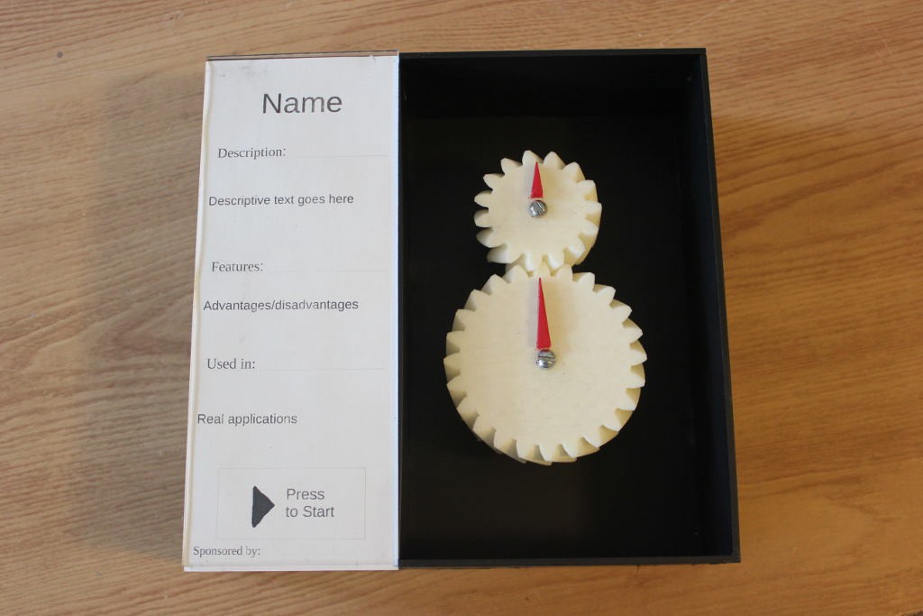
The first cell I started with a simple pair of gears. I downloaded some off GrabCAD, then modified them slightly to have a smaller inner diameter and an arrow on top to have a visual indicator of it as it turns.
After 3D printing them, I needed to figure out a mechanism to attach them to the cell. This is where things are going to get tricky for all the cells; not only the motion needs to be designed, but the fixture to hold the moving parts to the cell need to be designed as well. This will make all of the cells a little more time consuming than I'd like.
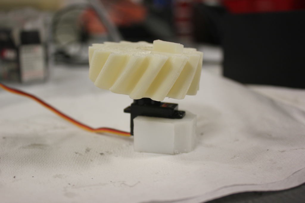
Since this is a rough draft of a cell, I didn't want to work too hard on making it perfect, so I took some HDPE blocks and carved them on the band saw and drill press to make them fit with some metal hardware. Hot glue was the final ingredient to get everything to stick. This is what the prototype cell looks like assembled:
Attaching the PCB was fairly straightforward, and I was fortunate to have measured the mounting holes correctly. Soldering everything on the PCB was a cinch, with only a few components required.
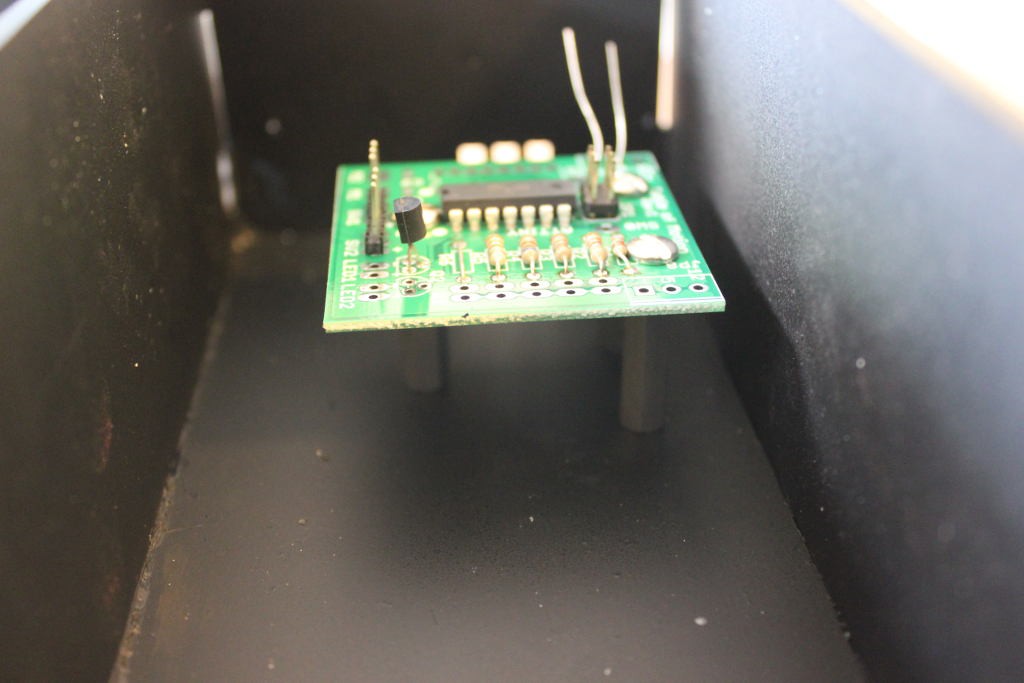
There was some firmware development as well, but I already had sample code for each of the different parts (LED, cap touch, and servo), so it was mostly a matter of copy/pasting things together. It was pretty nice that during the hardware validation step I had created a sample sketch to test each part individually.
Here is a video of the sample cell working. Touch the capacitive touch button and it turns on the lights and starts the action. It'll run for a few seconds, then turn itself off.
I'm conflicted about the light. It's too harsh, but it might be better in bright day in the museum. And it's too noisy. I'd like to reduce that. I also need to figure out a good way to get cap touch sensitive and reliable. Also, the connector hanging out the bottom will have to go away. The intent is to have a set of spring connectors sticking out the bottom, and when they make contact in the wall mount frame then power is supplied. These power rails would go up to the top of the cell, too, so that a stacked cell would get power.
Discussions
Become a Hackaday.io Member
Create an account to leave a comment. Already have an account? Log In.