 Bob Baddeley
This is a time-consuming project. There are way too many parts that need to be built.
Here's what's going on:
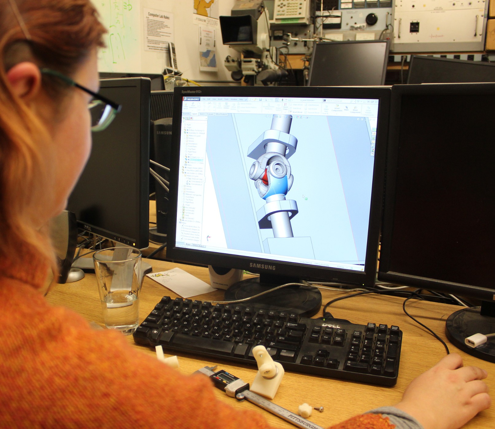
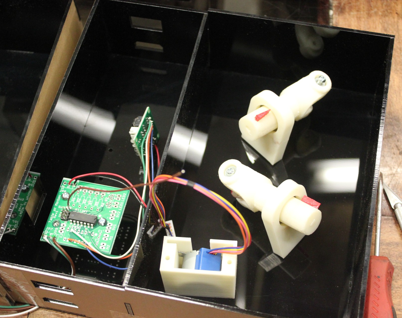
Building each of the elements takes forever. There are a few hours of design, followed by 3D printing the parts, then refining the parts to get them to fit together and work smoothly without friction, then doing the electronics and attaching everything to the element box, refining again to make sure it runs consistently, and then cleaning everything up and printing the text. It's a lot of work. Fortunately we have a growing library of consistent parts, like pieces that hold the stepper motors, and parts that hold shafts with bearings inside.
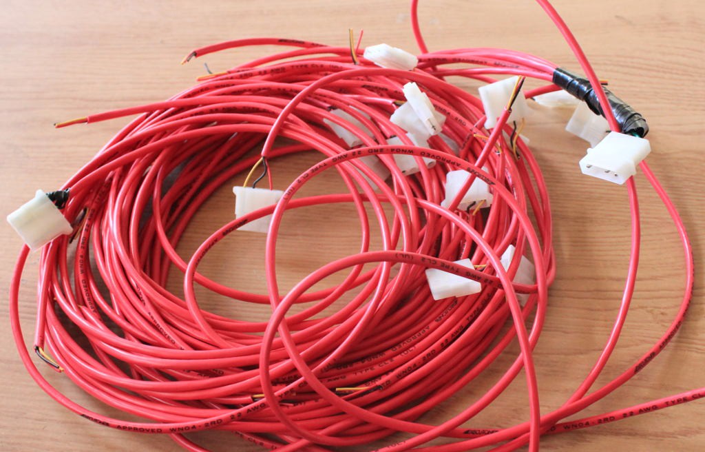
Cables are a pain. I've gone with ATX supplies, and I'm using 4 pin molex connectors. This is great because I have +5, +12, and ground, and that's what the ATX supplies pump out, with high current levels, and it's an easily sourced part. Yay for the ATX power supplies. However, I need to get that power up to each element in each column. Doing that requires lots of cables. Rather than use a terminal block or a huge stack of Y connectors (which are hard to source anyway), I decided to make a bunch of cables. They have one male connector to go into the ATX supply, and 5 female connectors. Each of the five has a different length, so that they can go from the bottom element up to the top element. The original design had each element supplying power through it via a connector on top and bottom, and merely stacking them would align them and pass power through. That didn't work so well, and I couldn't find a flush connector that would work. So I made a lot of connectors and I just pass them up behind the elements (there is some space in the wall).
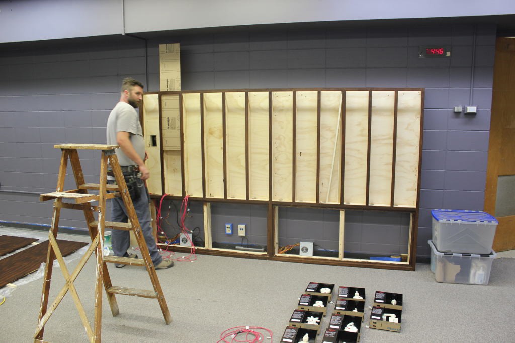
The wall is made. A carpenter built a frame that is 12 cells wide and 5 tall. It has about 2 feet on bottom to lift up the display, which also leaves room for cables and power supplies and a power strip. The wall has columns with a 9.25" width, and roughly 5 inch depth. Since our elements are 9" x 3", that's some extra wiggle room. The 1/4" on the sides means everything slides in fine and we can just shim it up, and the depth in back allows us to have the cables come up the back, plus screw heads on the back of the elements, and whatever else may be necessary in the future. They are also shimmed in the back with a couple loose pieces of wood so that they are held to the front. The whole thing is nicely finished, and large pieces cover up the top and bottom so that it is safe from human prying. It's also bolted firmly to the wall in case of little kids climbing (this is a museum exhibit after all). Large pieces of acrylic slide into each column and are held in place by the frame, preventing people from poking the elements, and allowing interaction through the capacitive touch, but with just a smooth surface that can easily be cleaned.
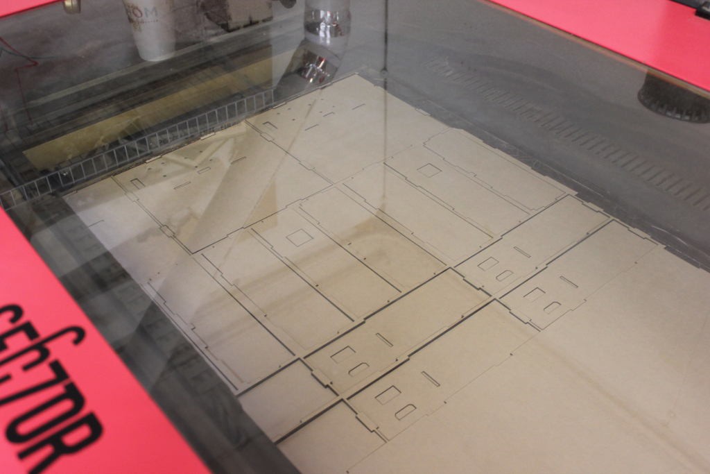
The element enclosures are all made. This took a full day of laser cutting to accomplish, but it's done. There are now roughly 75 enclosures. The exhibit only holds 60, but the extra allow us to have some in development that can get swapped in without leaving any spots blank at the museum. The enclosures are all taped together and look very clean and nice.
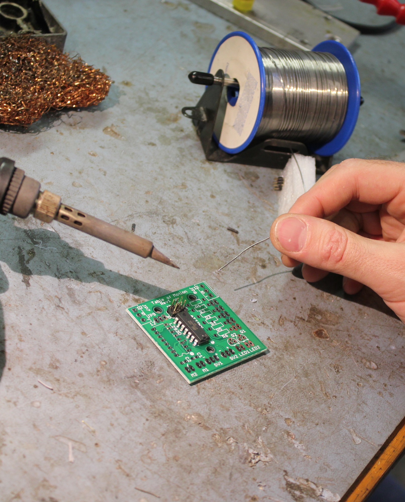
The electronics are mostly done being assembled. That's 60 PCBs with a few components on each, plus a connector for power. Many will have another PCB wired to it for the stepper motor driver, but not all, so I can't assemble all of those.
Firmware is working. I created a library that contains the stepper driver, the cap touch button sensing, and most of the timing. That makes the individual firmware for each element a lot shorter.
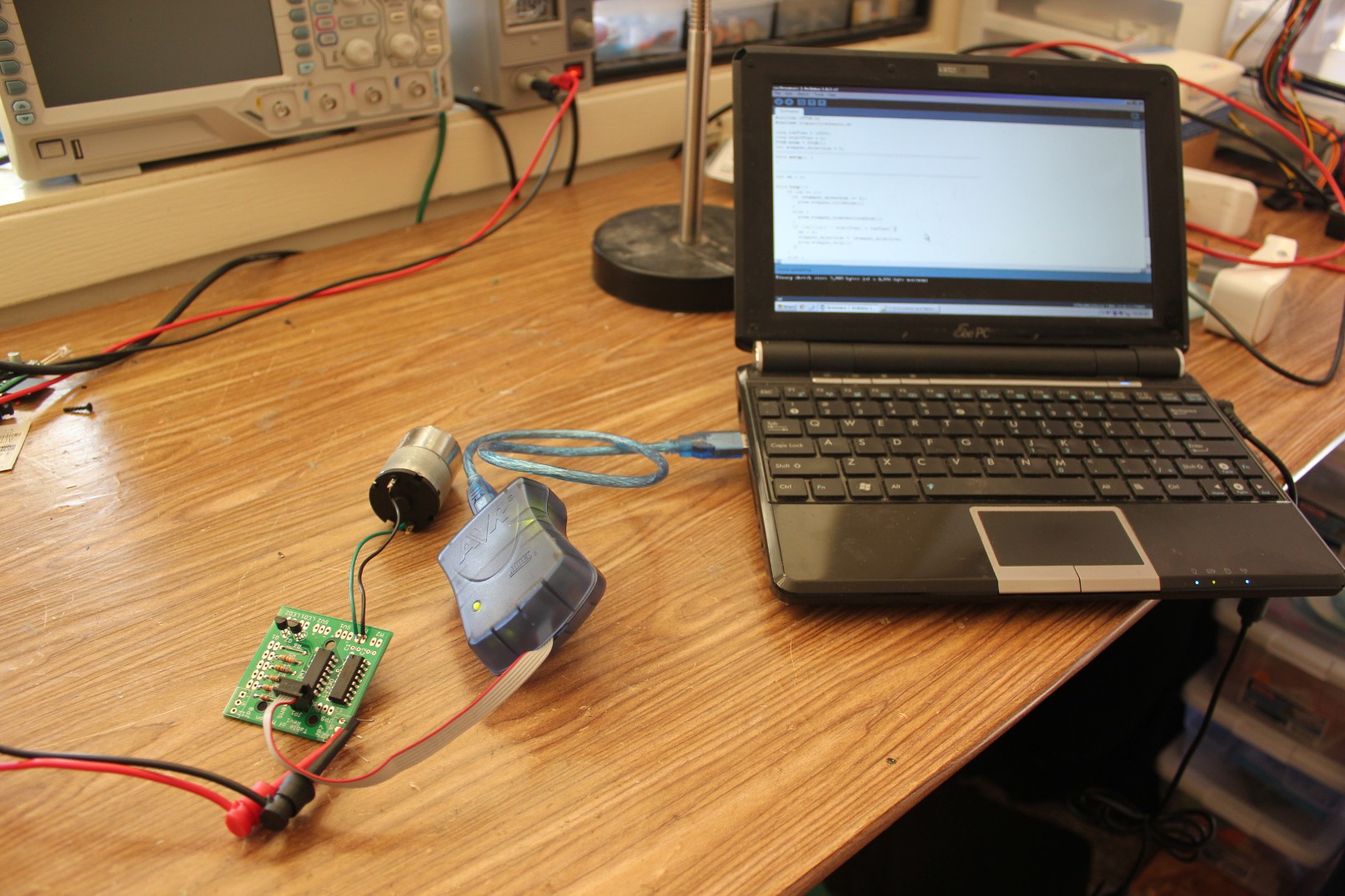
Cap touch is... touchy. I don't know how to get it consistent across all the elements, and it's a pain because even though they were fine during testing, once installed they are all over the place in sensitivity. I attached a capacitor to the sensor to smooth it out, and that helped, but not enough. I'm disappointed, but I'll keep plugging away at a solution.
Discussions
Become a Hackaday.io Member
Create an account to leave a comment. Already have an account? Log In.