The good news is the PCBs I ordered should get here Saturday. The bad news is there are horrible flaws in the design that would burn up one or more components. I may have jumped the gun in ordering those PCBs... stings.... Here's a list of them. The first 2 are from SJ Greenfield.
- Since the 9Vac source is grounded by the voltage divider AND the diode bridge, it shorts itself across the diode between pins 2 and 4 on the bridge every negative cycle. That diode bridge definitely would have smoked.
- SOLUTION: Go with a single diode half wave rectifier. This will require a larger smoothing capacitor.
- Resistor R4 should have a junction between R12 and R11.... Duh.
- Currently when the current transformer is disconnected, the switch in the stereo jack pulls the ADC line to ground. After looking at it again I think it would be better to send the divided 1.65V to the ADC so I can calibrate that measurement.
- Button1 is tied to pin RA7 on the PIC. RA7 just so happens to not have any interrupt associated with it, nor is it a remappable pin. Nice.
- Turns out the CSN pin on the nRF24 is more than just a simple chip select. You know, the simple kind that just enables/disables the entire chip. It actually needs to be pulled high and low when sending commands. Go figure.
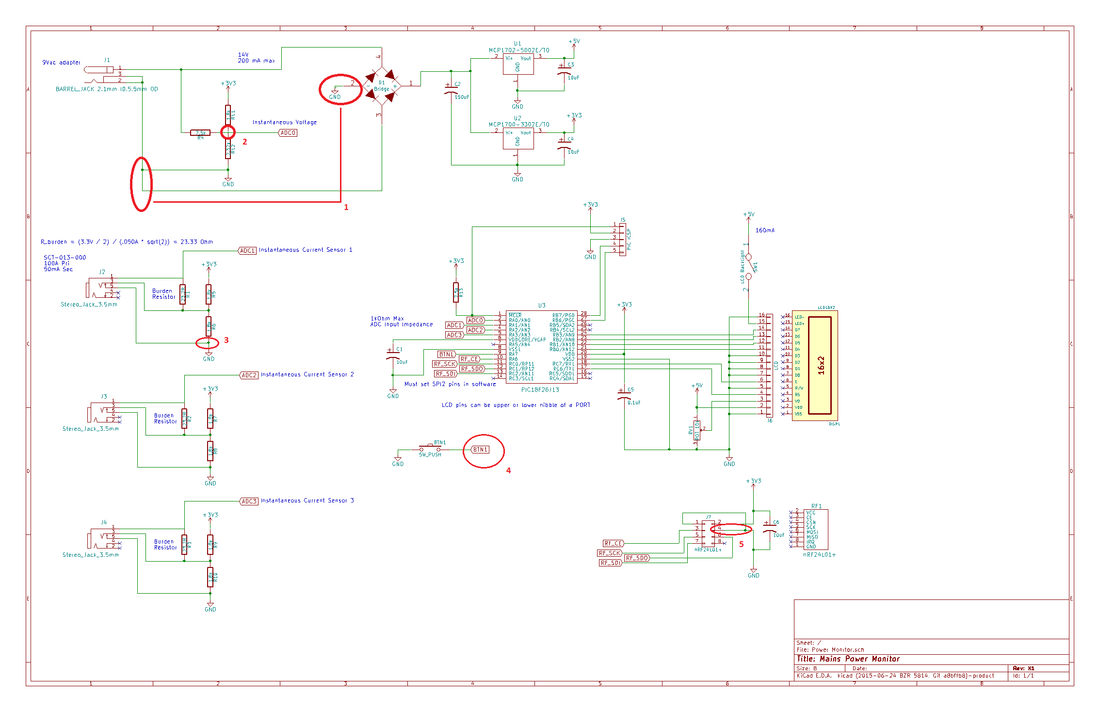
Let me know if you guys notice anything else!
Discussions
Become a Hackaday.io Member
Create an account to leave a comment. Already have an account? Log In.