Close
0%
0%

A multithreaded blinking theremin powered by VIPER

Find out how to have fun by annoying people with your brand new multithreaded blinking theremin powered by VIPER! #viperizeit

Similar projects worth following
In this hack, we'll see how to make a simplified theremin-like instrument that changes the pitch played as you wave your hand over an Infrared Proximity Sensor. In addition you can easily vary the length of the "beat" and drive various blinking LEDs (seemingly) all at the same time. It's the magic of multi-threading... it's the magic of VIPER!

VIPER is an easy to use development suite for the high level design of interactive objects ready for the cloud and the IoT. With VIPER creatives, designers and professionals can develop in Python for Arduino DUE, ST Nucleo and most of Particle (formerly Spark) products, and similar boards using paradigms and features typical of PC and mobile programming.

Enjoy!

The theremin is an experimental musical instrument invented by the russian physicist Lev Sergeevich Termen in the 20's. Without physical contact, two antennas can sense the position of the theremin player's hands in space and use it to control the frequency and amplitude of the sound. The theremin has been used in classic movie soundtracks such as The Day the Earth Stood Stilland The Thing from another world.

In this hack, we'll see how to make a simplified theremin-like instrument that changes the pitch played as you wave your hand over an Infrared Proximity Sensor. In addition you can easily vary the length of the "beat" and drive various blinking LEDs (seemingly) all at the same time... it's the magic of multi-threading!

Despite its apparent complexity, this project requires very simple electronics, as most of the dirty jobs is done for you by VIPER, the software used for programming the theremin.

VIPER (Viper Is Python Embedded in Realtime) is an easy to use development suite for the high level design of interactive objects ready for the cloud and theIoT. With VIPER creatives, designers and professionals can develop in Pythonfor Arduino DUE, ST Nucleo and most of Particle (formerly Spark) products, and similar boards using paradigms and features typical of PC and mobile programming.

DISCLAIMER

Even though VIPER is a professional and performant development suite, this tutorial shows how to make a non-professional theremin, played by a non-professional thereminist, as shown in the "Intro" video.

However, we are quite confident that you will get better outcomes than Sheldon :)

So, let's go!

  • 1 × Sharp infrared proximity sensor (GP2Y0A21YK) or other analog distance sensors
  • 2 × 1 kΩ resistor
  • 2 × low-power LEDs (red and green)
  • 1 × piezo buzzer
  • 1 × rotary potentiometer

View all 9 components

  • 1
    Step 1

    Assembling the circuits

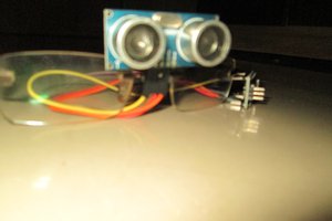
    • Each Sharp IR proximity sensor has three pins. One is the power input, which we connect to 3.3V. Another is the ground that we will connect to one GND pin. Lastly, there is the analog output that varies from 3.1V at 10cm to 0.4V at 80cm. The analog output pin needs to be connected to an analog input. Here, we used pin A5.
    • Piezo buzzer uses a special crystal that expands and contracts as an electrical signal passes through it. This will generate a tone that we can hear. One pin of the piezo buzzer goes to GND connection and the other to digital pin D7 (or another pin with PWM feature if you use Spark Core, such as A4).
    • A rotary adjustable potentiometer has three pins. Connect 3.3V to an outer pin, GND to the other, and the center pin will have a voltage that varies from 0 to 3.3V depending on the rotation of the pot. Hook the center pin to an ADC on a microcontroller and get a variable input from the user! Here, we used pin A2.
    • To build the red LED circuit, connect one end of the resistor to pin D8 (or D7 on Spark Core). Connect the long leg of the LED (the positive leg, called the anode) to the other end of the resistor. Connect the short leg of the LED (the negative leg, called the cathode) to the GND.
    • To build the green LED circuit, do as for the red LED circuit but connect the resistor to pin D6.
  • 2
    Step 2

    Programming the board with VIPER

    Using VIPER is very easy! Let’s see how step by step:

    1. Download the Windows, Linux or iOS installers from VIPER Download page(security messages can be shown on Windows, please accept and go ahead, this issue will be solved soon).
    2. Install it (here’s a tutorial on how to install VIPER IDE) and launch it through the VIPER shortcut.
    3. Create a VIPER user through the dedicated button. Check your email and verify your new account by clicking on the provided link. Why registering? With a VIPER account you can: join the VIPER community; save your projects on the cloud and access them from different devices; automatically receive updates of the VIPER IDE, VIPER VM, Libraries, and new examples.
    4. Once the account has been verified the VIPER IDE automatically logs you into the VIPER cloud (the first time you create a user account an IDE restart can be required. If you have sign-in issue please restart the IDE).
    5. Connect your board and rename it as you prefer in order to easily recognize it in future.
    6. To make the board usable, you need to Viperize it. Viperization is the process of installing the VIPER VM (Virtual Machine) on a board. The process can be launched by clicking on the dedicated button available on the VIPER IDE top bar.
    7. Create a new project, copy the code from github, compile your script and upload it in the board. Follow the IDE messages, some boards require a manual reset during the upload process.
    8. Enjoy your running VIPER script!
  • 3
    Step 3

    Explaining the code

    Why using VIPER

    One of the concepts many people find challenging when beginning to write code for microcontrollers is how to manage multiple hardware-related tasks, seemingly all running at the same time. Designers are consequently frustrated by the difficulties in implementing such functionalities in microcontrollers.

    In order to solve these pains, VIPER supports all the most used high-level features of Python like modules, classes, multithreading, callbacks, timers and exceptions, plus some custom hardware-related features like interrupts, PWM, digital I/O, etc.

    Each thread in VIPER is a sort of separated and parallel process that runs autonomously on your board. A thread requires a function to be executed as input for the definition. The same function can be instanced by various thread giving you the possibility to write very concise and readable code. With threads you can design your algorithm architecture assuming parallelism that is typical of high level. More info here.

    Inside the code

    The script is implemented using 4 threads that run in parallel. One thread is used for acquiring and normalize the analog signals acquired through a potentiometer and a IR proximity sensor. The other three threads are used to instantiate a generic blink() function that drives two LEDs at different frequencies and a generic buzz() function that drives a buzzer at different frequency e length of the sleep (to create a "beat" effect), calculated on the basis of the acquired analog signals.

    Get the script from github. The code has a ton of comments. Just a couple of notes.

    • delay() vs. sleep()

    In Arduino/Wiring using delay() has a side effect - the Arduino does nothing for that while. To get two or more "actions" to run independent of each other, you cannot use delay().

    In VIPER the sleep() function suspends the current thread for time expressed in time_units BUT all the other threads are free to continue their execution!

    • VIPER built-in functions

    VIPER VM extends Python with built-in functions to handle the General Purpose Input Output pins of the embedded device. These functions resemble the ones used by Arduino, but are more flexible.

    analogRead() vs. adc.read()

    The analogRead() function is provided as a built-in to ease the passage from the Arduino/Wiring to VIPER.
    However the preferred way to read an analog pin in VIPER is:

    # import the adc driver

    import adc

    x = adc.read(pin, samples=1)

    Reads analog values from pin that must be one of the Ax pins. If samples is 1 or not given, returns the integer value read from pin. If samples is greater than 1, returns a tuple of integers of size samples.

    analogWrite() vs. pwm.write()

    The Arduino's analogWrite() function provides a simple interface to the hardware PWM, but doesn't provide any control over frequency. The analogWrite() function is provided as a built-in to ease the passage from the Arduino/Wiring to VIPER. However the preferred way to use pwm in VIPER is:

    # import the pwm driver
    import pwm

    pwm.write(pin, period, pulse, time_unit=MILLIS)

    The state of pin is periodically switched between LOW and HIGH according to parameters:
    - period is the duration of a pwm square wave

    - pulse is the time the pwm square wave stays in the HIGH state

    - time_unit is the unit of time period and pulse are expressed in time_unit

    Have fun!

    You can start from this very simple example code to develop the behavior you prefer. Of course there is plenty of room for improvement, such as:

    • adding a volume control
    • taking advantage of the smartSensors library instead of mapping the analog input values range by hand

    Feel free to suggest your own ideas, and have fun annoying people with your brand new multithreaded blinking theremin powered by VIPER!

    Luigi F. Cerfeda (@L_F_Cerfeda) - VIPER team

View all 3 instructions

Enjoy this project?

Share

Discussions

Similar Projects

Does this project spark your interest?

Become a member to follow this project and never miss any updates