 SHAOS
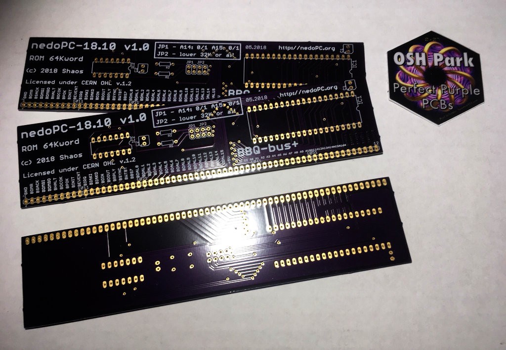
SHAOSA few days ago I received 3 PCBs from OSHPark:
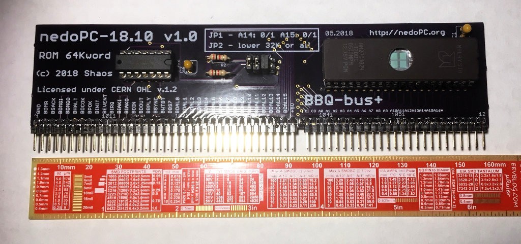
and today built one of them:
It could be inserted into large solderless breadboard together with CPU module for testing without backplane:
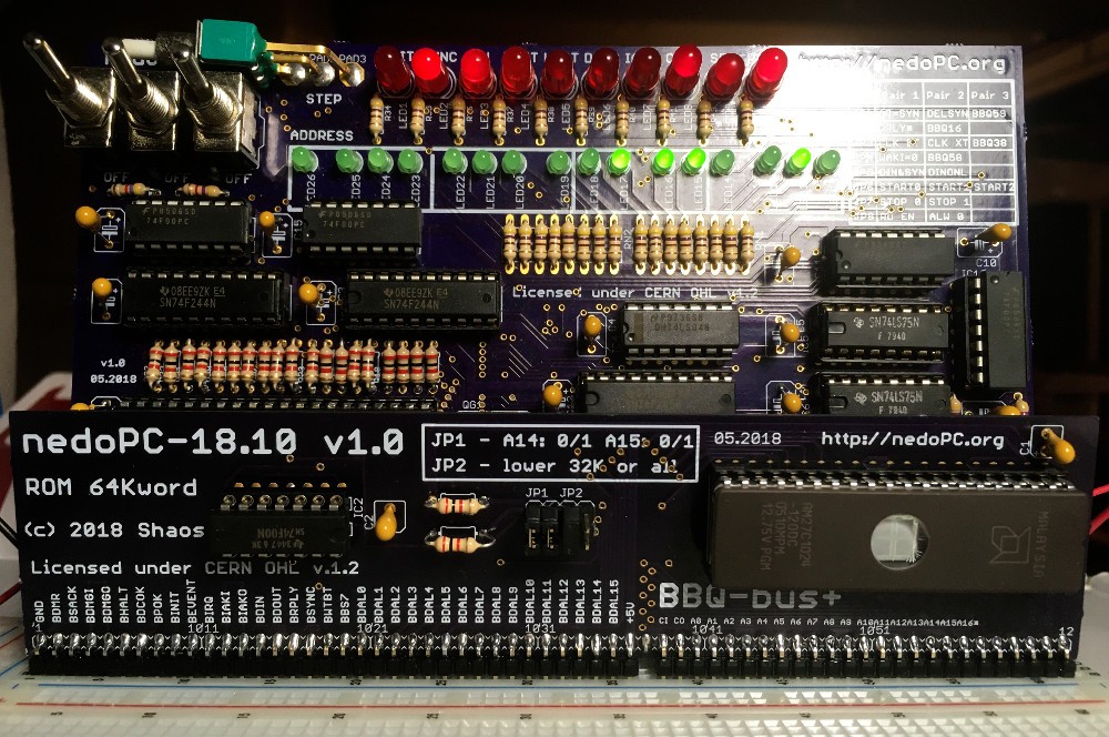
I flashed ROM with very simple program - a lot of NOP instructions (for PDP-11 it is word 0240 or 0x00A0 that should be inverted and stored to ROM as 0xFF5F because our databus in PDPii is inverted). With 1 MHz oscillator we see this:
It is possible to calculate that most significant address LED (green one on the left) blinks about every 0.4 seconds and it sounds about right because 1 NOP is 12 external ticks (6 internal) and 32768 NOPs (whole address space) with 1 MHz external clock should be done in 1/(1000000/12/32768)=0.39 sec.
Now I should write something more complex for it ;)
P.S. Also I successfully tried 3 MHz, 4 MHz and 10 MHz oscillators on black VM2s with 1 dot on the package (rated 10 MHz on the factory), but higher frequencies expectedly failed to work (namely 16 MHz and 20 MHz).
P.P.S. Black VM2s without dots (highest rated) appear to be working with 16 MHz oscillator!!!
P.P.P.S. One recently bought black КР1801ВМ2 with dot (so it has to be <=10MHz) worked not only on 16 MHz, but even looked functioning on 20 MHz ( but not 25 ; )
Discussions
Become a Hackaday.io Member
Create an account to leave a comment. Already have an account? Log In.