 zittware
I can’t claim originality here... as I remember the XENON machine at a past TPF which had NIXIE tubes instead of the standard VFD displays. I always thought they were cool.
Now that I’m designing Star Trek: The Mirror Universe; I’m thinking that I want to put NIXIE displays in the machine instead of stock Bally displays.
I’ve been doing some design work; and have come up with the following schematics which use the IN-12A tubes from Russia. They are nearly the same digit height as a stock display and are relatively inexpensive compared to other tubes.
Just put the finishing touches on the silk screen for the Base board for the Nixie display.
Here’s a image of the boards as they stand today.
Base Board: 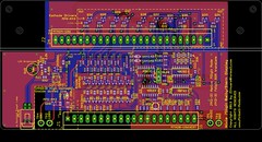
Display Board:
New features added:
1) The “Right angle” Display board has surface mount LEDs under the tubes; the idea here is that when the display is “active” meaning PlayerX is up... the switched LAMP driver on the side of the display turns on these LEDs causing them to backlight the display ... to help identify which player is active. A Brightness POT on the baseboard controls the brightness.
Opto-Isolated the “lamp” input from +5V logic.
2) I added decode logic to support 7digit display ROM hacks:
Update 6 Digit Bally pinballs to 7 digit
where buy D5 =1= D6 causes the 7th digit to become active. U3 & U4 provide this functionality.
Feature is jumper selectable to for native 7digit or Rom-Hack 7digit mode via JP1.
3) Clearly labeled Test Points with voltages. Added 80V test point.
4) Additional decoupling caps near U1,U2,U3 and well as a bulk cap for 5V.
5) Nixie tube display board is at a “right angle” to the base board (like original); but is back set far enough so “front” of IN-12A displays are near same position as the VFD display.
6) HV areas “inside” dotted lines. Generous ground planes to help with thermals.
7) Same PCB sizes as original.
The Schematics are posted here for review... I’ve never designed a display before... so will probably need to do some design tweaks once I get the Tubes in.
http://www.Pinball-Mods.com/blogs/wp...ally7Nixie.pdf
At this time; the design remains my copy-protected property! Once I've proven the design; I'll consider open-sourcing the design for others to build.
I went 7digits instead of 6... so they can be used in other machines. I’ll either de-pop NIXIE_A7 or figure out how to make my Bally FW run a 7digit display.
3/23/2013:
I hand assembled the base and display boards and soldered them together.
I didn't want to commit the untested display to my Bally Star Trek... so I needed to figure out how to facilitate debug.
First problem was how to supply 190VDC to the HV section. Some googling found me some 555 timer circuits which would run off of a 9V.
Had most of the parts except a 250V 4.7uf cap and a pot. A trip to Frys solved that problem.
A bread board and an ATX power supply and I had a 190V psu. The ATX supply provides +5v to the display and +12V to the 190V psu's input.
Here’s a picture of the prototype 555 190V Nixie supply: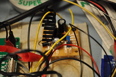
Initial debug turned up a dumb assembly mistake..– I swapped U1 & U2 despite the clear labels on the silkscreen.
I hardwired the display inputs to only lite digit 1 and display an 8 (1000b). 8 because it's the digit which uses the most current given the largest area. This will allow me to verify the anode current before committing to a final anode resistor. To "latch" the 8 digit; I used my RatShack Logic pulser to toggle the LE pin.
I was able to empirically calculate the Anode resistor using the built-in test point and pot. 21.4k... now I just need to find some 22k 603 resistors to make it work. 21.4k gives me 2.5mA of anode current which is typical for the NH-12A tubes I’m using.
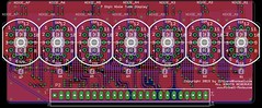
Here’s the top view of the display boards: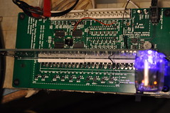
And the money shot for the backlite display:
I decided early on that I wanted the backlite to be purple rather than some other color because I thought it’d contrast nicely against the orange digits.
You can see the testpoint and Anode pot right below the Nixie tube. Obviously; these will be de-poped for “production” boards.
Here’s a picture I just thought was cool. A result of playing with camera shutter times: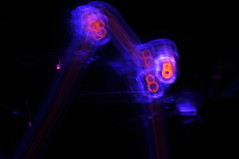 With the resistor calculated; I need to focus on creating a Display tester so I can run the display thru all the digits and functions.
4/9/2013: More debug this wkend seems to point to the 4555 1to4 decoder circuit.
I pulled the tristate buffer (u4) and solder bridged the outputs of the 1to4 decode straight to the transistors thru a 9.1k resistor.
The display does the same thing without U4.
This points to U3 (cd4555) being the culprit.
Now; given I’ve already verified 7 digit emulation with the arduino which doesn’t work in the machine; seems to be a clue.
I’m leaning toward the output of the MPU being TTL compatible; but not CMOS compatible. I don’t think the signal to the displays is meeting CMOS high requirements for digits 5&6. According to my mpu schematics; the digit enables are driven directly by the output of a 6821 PIA.
So; next step is going to be to wire in an oscope to see what D5’s levels are.
Then figure out how to solve if hypothesis proven.
This pretty much sums it up: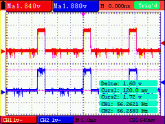 PeakToPeak; my displays (digit enables) are only getting 1.6V for a high. Well below the cmos “good” for a 1. This is measured at R44 and R43 closest to the connector on stock displays.
This is the reason why my Nixie design isn’t working. I can design around this with either a transistor or some other translation logic; just not sure why the value is so low.
I see why it works on stock displays as all we need is for the high to be > ~0.7V to turn on the digit enable transistors in the original design.
Just need to confirm with other pins / people that they see similar results. I only have the one Bally Star Trek; no other era pins.
By confirming other pins; we can determine if this is a design change is warranted.
4/11/2013: I did some "dead bug" rework to the existing display; basically epoxing two SMT 2N3904s to the top side of U3. I cut some traces and soldered a 20K ohm pull up between VCC and the collector of the transistors. Emitters were tied to ground. Bases were connected to the series resistors currently present in the schematic.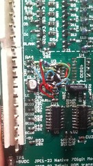
The goal here is to work out the kinks in the design so they can be incorporated into a FAB B board and be relatively confident the design will work out of the box.
Because the BJTs are single transistor inverters; I needed to rewire the input to U3. I wanted to reuse the existing CD4555B chip already present to keep the design similar. Turns out that by swapping A & B inputs vs the schematic; the following Boolean logic become obvious:
U3A Q1 = !B*A = D5
U3A Q2 = B*!A = D6
U3A Q0 = !B*!A = D7
Remember that when the MPU is driving A5 or A6 high; the BJTs invert that to be an active low. So the boolean math makes it logical.
The result (finally):
Click here for YouTube movie
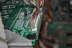
Here are some pictures of the display installed in my Bally Star Trek machine: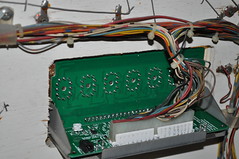
 Known issues:
Digits are too light when running in multiplexed mode (in a real machine); plan to drop the anode resistor to ~2.7k from 22k to brighten the digits. Not a good idea for non-pinball machines which aren't multiplexing the digit enables; but should be fine for more machines.
Need to "fix" the native 7 vs emulated 7 digit jumper selector given the need to invert D7 in native mode.
5/15/2013:
I’ve completed assembly of FAB B of the NIXIE tube displays. The emulation and 7 digit native modes work as designed. I’ve posted a youtube video with it installed in the backglass.
http://www.youtube.com/watch?v=YcyABnz11KA
Obviously; the 7digit modes do not work “ideally” with a machine designed for 6digits. I may spend some time in the future to make a 6 digit “right angle” board if there is enough interest.
Need to confirm in a 7digit machine that it works properly. I already have a volunteer.
Next step is to write a blog post with schematics and pictures.
Need to send the boards out for Black PCB fabbing.
Discussions
Become a Hackaday.io Member
Create an account to leave a comment. Already have an account? Log In.