0%
0%
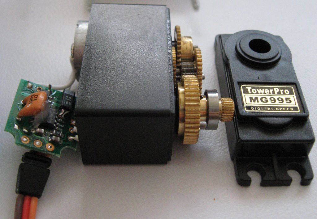
127 TowerPro Servos, one I2C interface.
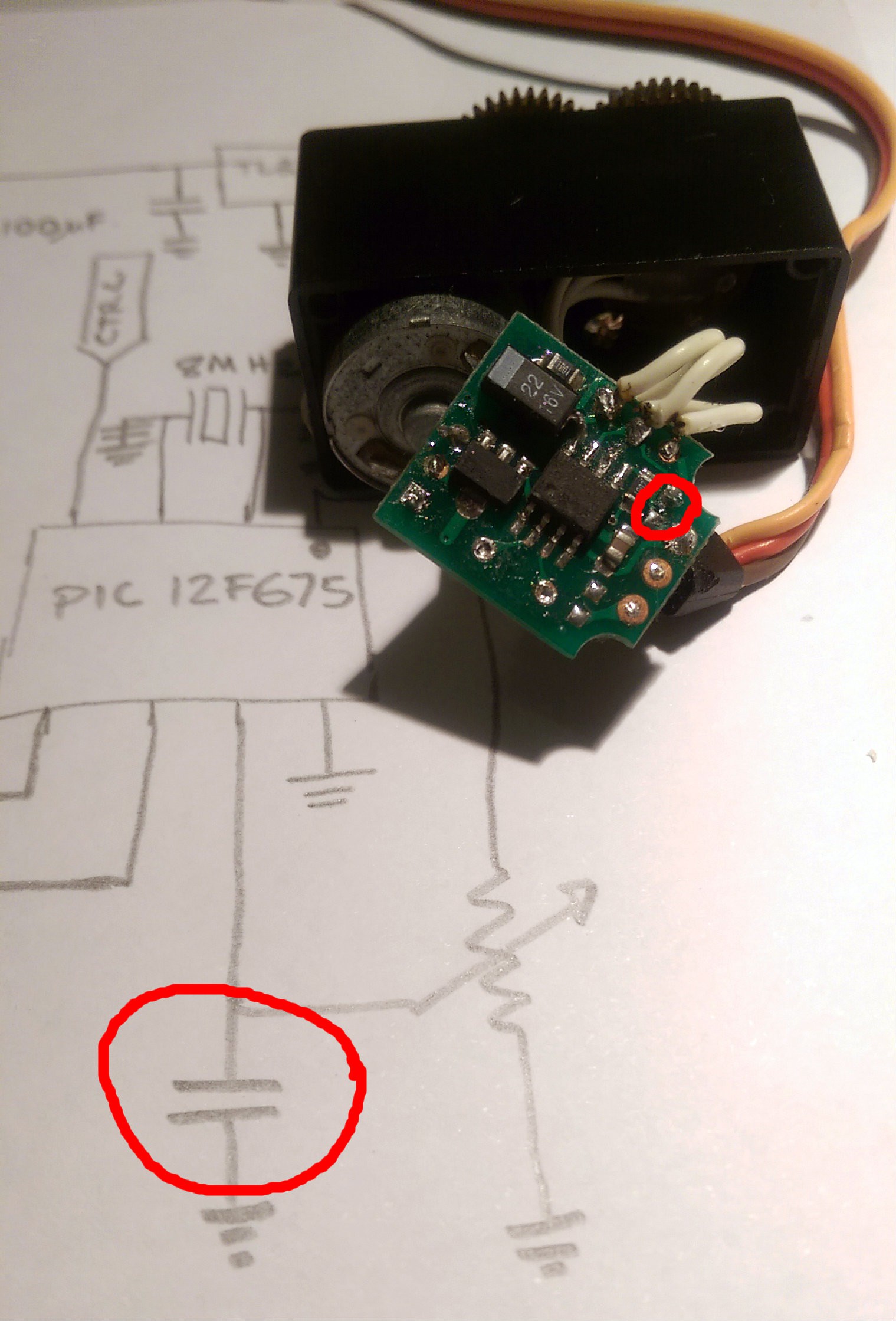
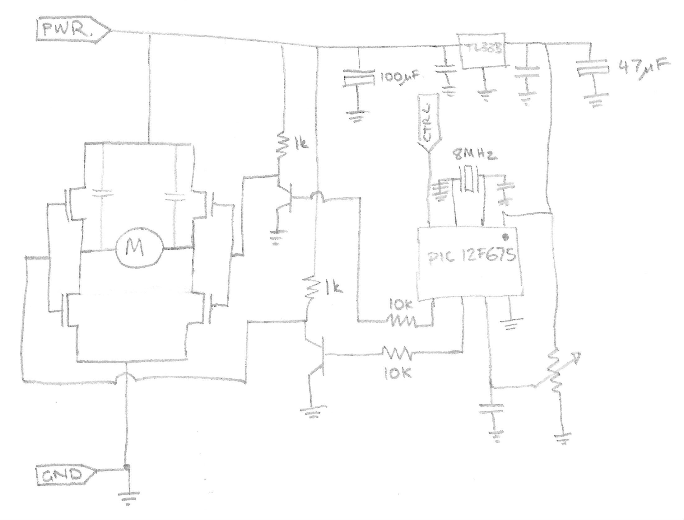
Taking the cheap and strong TowerPro MG995 servos (and siblings) and reprogramming them to accept commands and report position via I2C.
Become a Hackaday.io member
Already have an account? Log in.
Just one more thing
To make the experience fit your profile, pick a username and tell us what interests you.
Pick an awesome username
hackaday.io/
Your profile's URL: hackaday.io/username. Max 25 alphanumeric characters.
Pick a few interests
Projects that share your interests
People that share your interests

 Nick Sayer
 Mike
Mike
 Shranav Palakurthi
 John Lonergan
Any issues with noise on the I2C lines? Great idea!