 Marcin Byczuk
Power supply
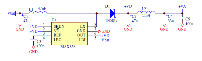
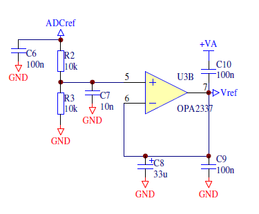
All circuits in the Biomonitor operate at 3.3V. To supply the Biomonitor from one 1.5V battery or 1.2V NiCd/NiMH cell DC/DC converter was used. Analog and digital parts of the Biomonitor have separate supply (VA and VD). For proper operation of amplifiers a virtual ground is formed (VREF) using ADC reference voltage.
A biosignal amplifier (one channel)
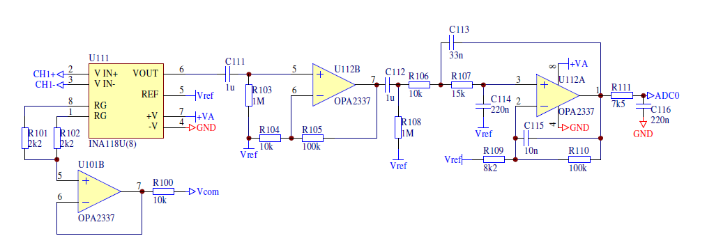
Weak bioelectrical signals are amplified and filtered by 3-stage differential amplifier. Its first stage contains precision instrumentation amplifier INA118/INA126 (see figure). Common mode voltage from measuring inputs (CH+ and CH-) is buffered and then used by reference electrode driver. The next stage is connected trough RC high-pass filter to remove DC component. The last stage consists of band-pass filter with the upper cut-off frequency of about 60Hz, so it is recommended to use sampling frequency of 200Hz to avoid an aliasing.
Reference electrode driver
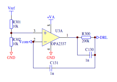
Common mode voltages from both channels are used to drive reference electrode. It allows minimizing common mode voltage on measuring inputs and thus reduces mains interferences in measured signals even if CMRR of the instrumentation amplifier is not sufficient.
Bluetooth module
For wireless transmission of all data the WRAP THOR module from Bluegiga was used. It is a complete Bluetooth radio with Bluetooth stack and ASCII Interface firmware, which makes Bluetooth stack invisible for the application. The module communicates with the microcontroller via UART port. All Bluetooth operations (e.g. searching devices, making and releasing connections etc.) are done by sending simple commands (e.g. INQUIRY, CALL). After making a connection data is sent and received as in wired serial connection.
CPU
The Biomonitor is controlled by 8-bit RISC microcontroller – ATmega8L. It is equipped with 8kB of FLASH program memory, 1kB of SRAM, UART, 8-channel 10-bit ADC with internal 2.56V reference voltage and SPI serial interface which allows easy uploading of a new firmware. Inputs 0 and 1 of the ADC (pins ADC0 and ADC1) are connected to the differential amplifiers. Channel 6 of the ADC (ADC6) is used for measuring battery state. Internal reference voltage, available on the pin AREF, is used by supply unit.
The Bluetooth module is connected to the UART pins of the microcontroller (RXD and TXD) and pin PD2 (RESET_IN of the BT module). Pin PD3 (INT1) is connected to the user button. SPI pins, RESET, ADC2 to ADC5 and some I/O pins are available on the extension board / programmer connector.
CPU uses external 7.3728MHz crystal resonator for proper generation of standard transmission frequencies of the UART (e.g. 115200bits/s).


 Jithin
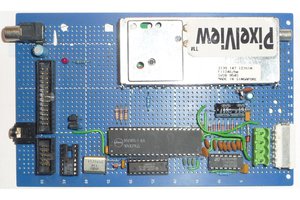
 Keith
Keith
 Nicolò
I've used Ag-AgCl electrodes