 Johnny
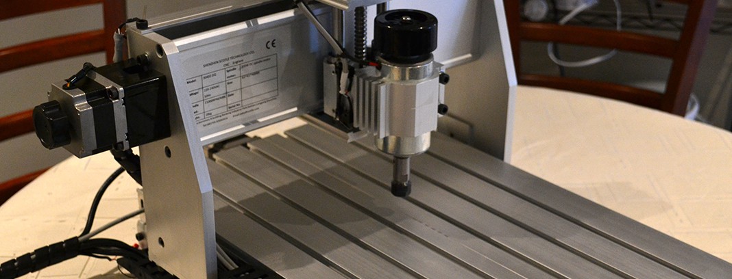
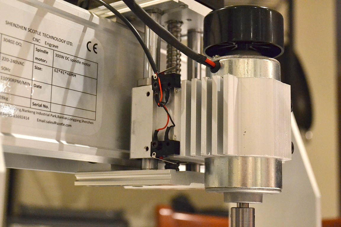
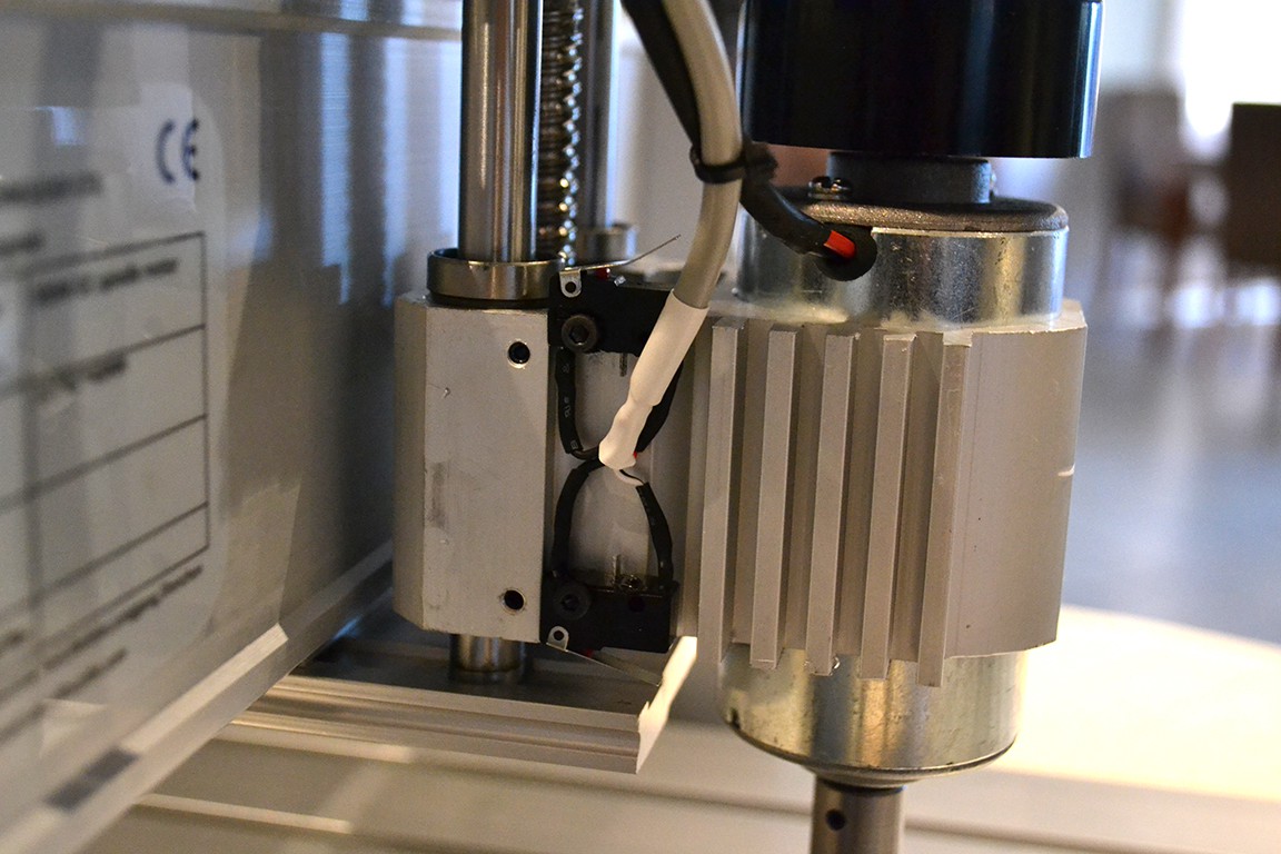
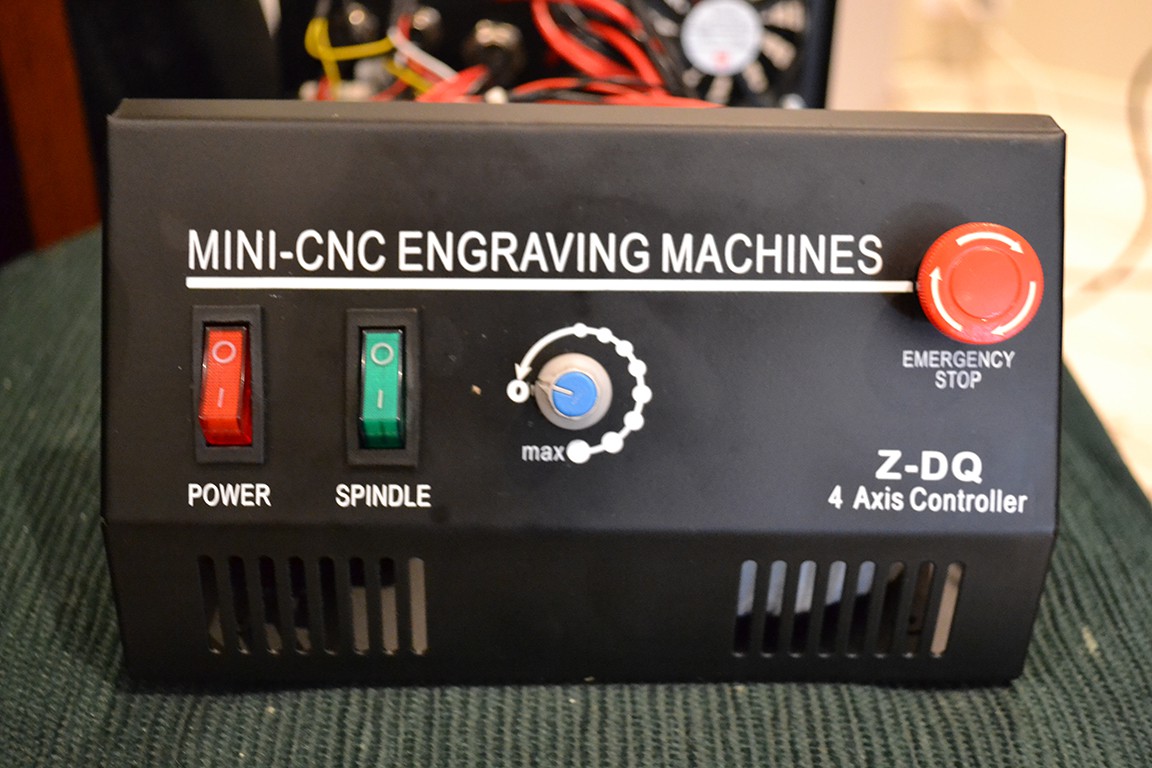
The "3040" in the model 3040Z-DQ means the working platform is 30cm by 40cm, in reality you can use about 27x37cm. The "Z-DQ" model uses NEMA23 stepper motors, ball screws, and has a 230W DC spindle motor.
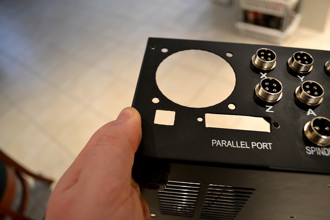
These Chinese CNC machines on ebay are good quality and cheap, but require that your computer has a parallel port. Who still has one?
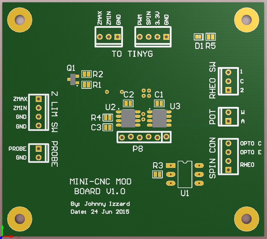
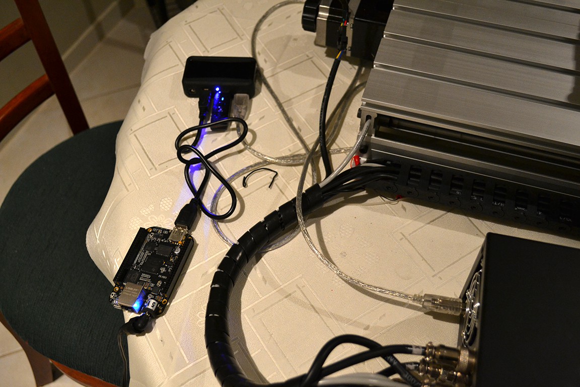
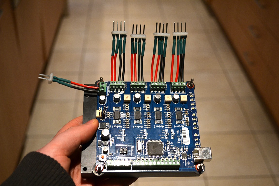
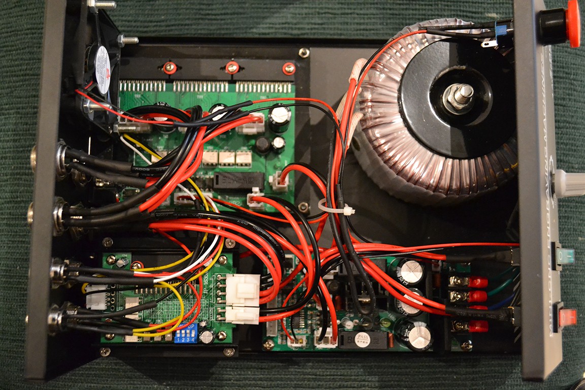
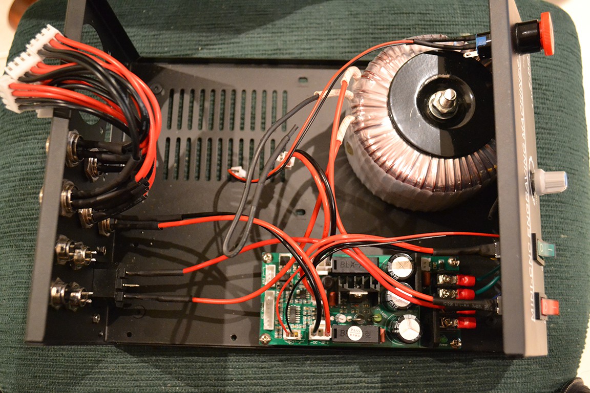
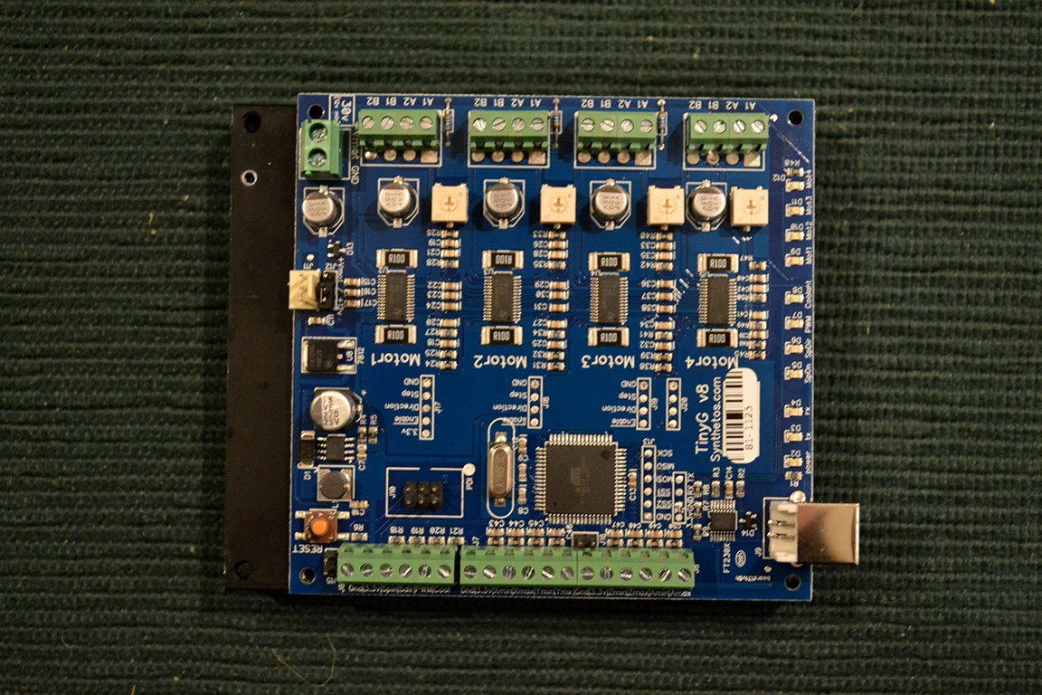
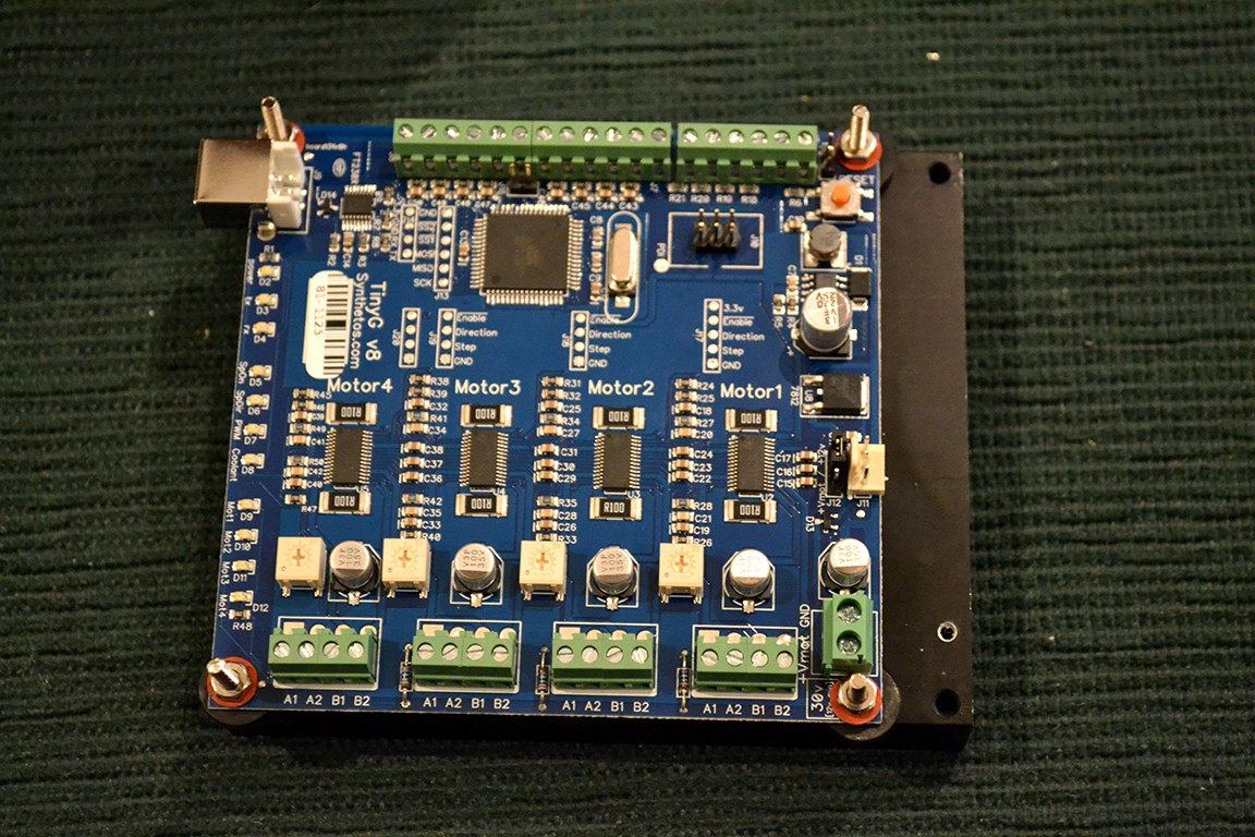
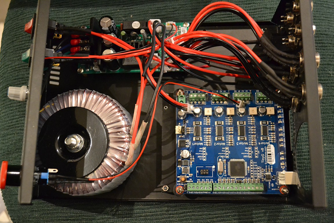
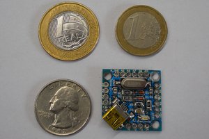
As you can see in the project logs, I swapped out the origional controller for a TinyG v8, which has USB and could be used with many different G-Code senders.
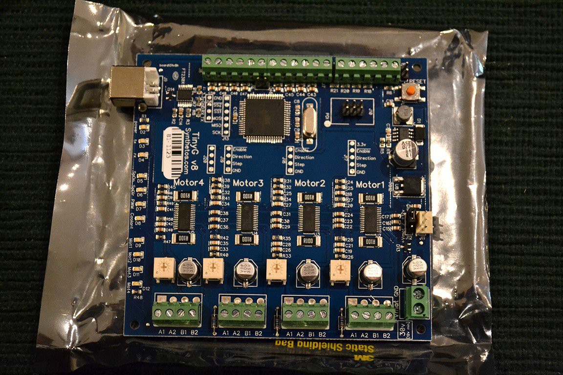
Years pass and I found my TinyG v8 board to be very unreliable. Randomly a axis will corrupt it's saved G54 origin during a job. This has resulted in several failed jobs! Also I've had bugs from day 1 that still haven't been fixed (4 years on!) e.g. Real-time Work Position (G54) at some point stops being updated/displays zeros (same issue regardless of g-code sender). It seems Synthetos has stopped supporting it's TinyG v8 users in favor of the TinyG G2.
I use a X-Carve at work running GRBL which I've never had issues with, therefore I'll for now stick to GRBL.
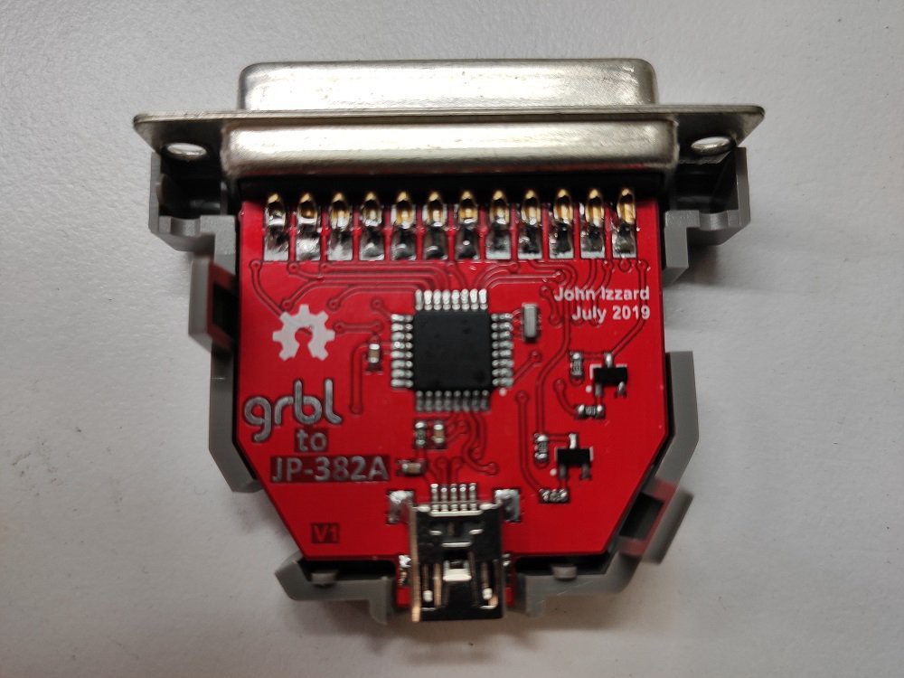
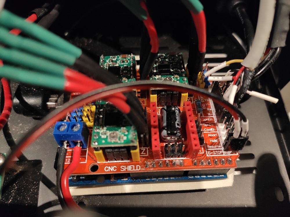
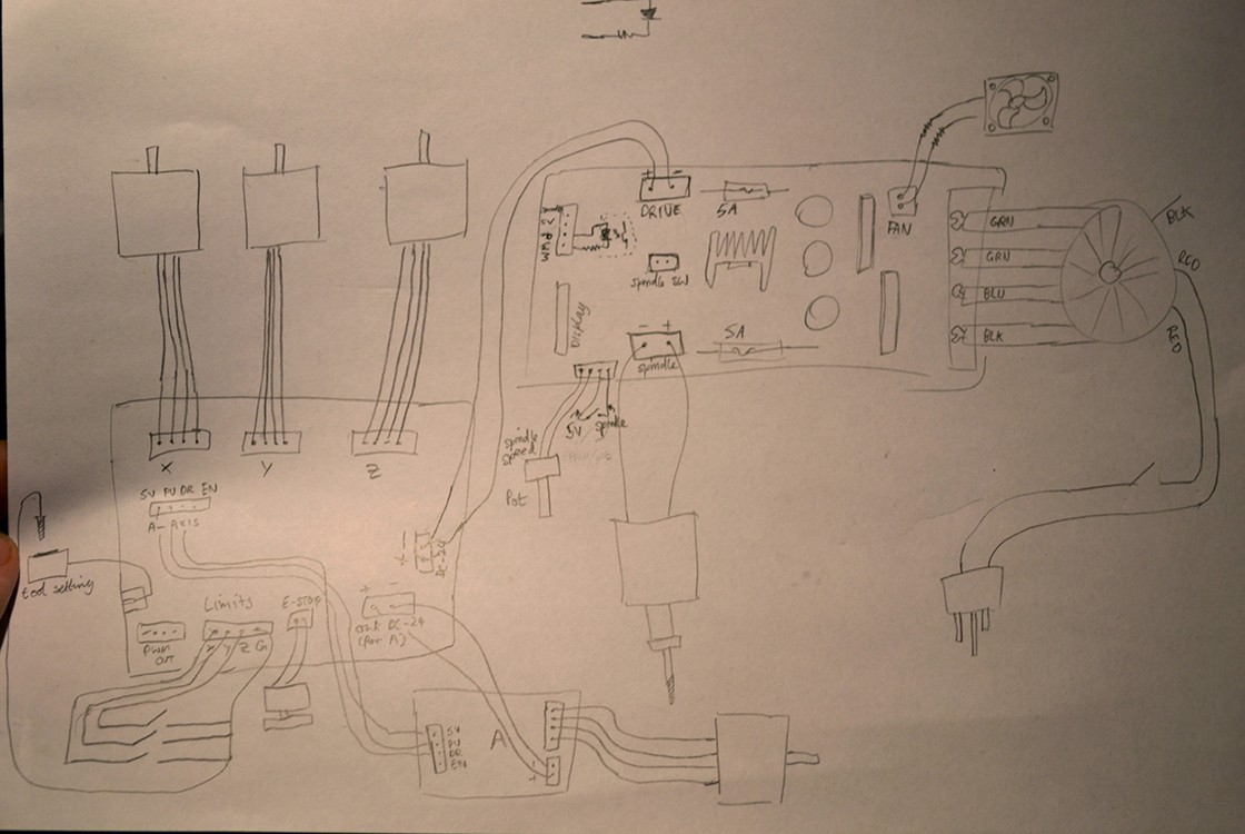
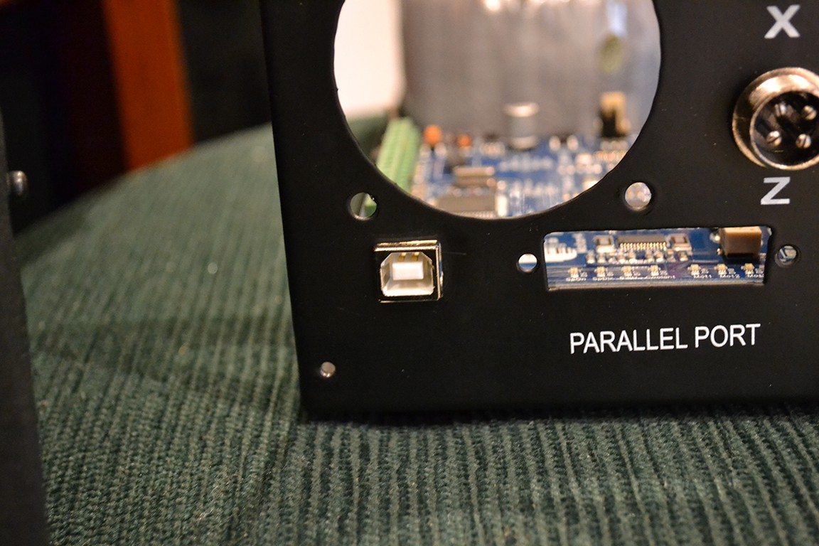
It's possible to avoid all the controller box modifications I've made if you keep the original stepper controller and connect an arduino running GRBL to the parallel port (see my GRBL to Parallel Port project). Plus this makes things easier if you decide to change controllers in the future. ESP32 GRBL is cool because it can run jobs off an SD card and be controlled over wifi.
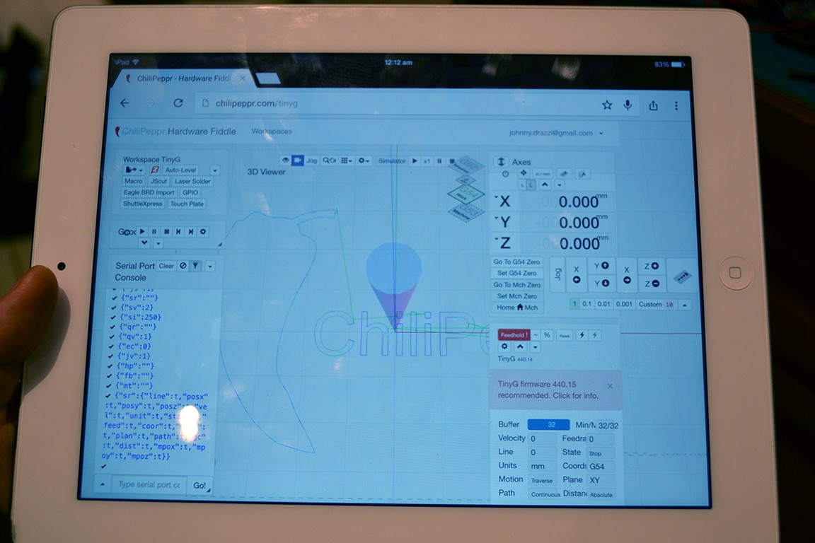
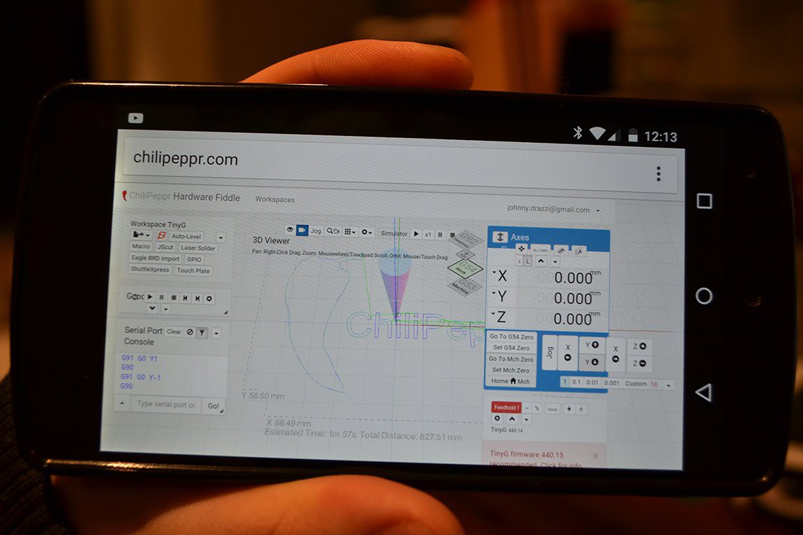
The G-Code sender I currently use is called CNCjs. I highly recommend it for GRBL/Marlin/Smoothie/TinyG.
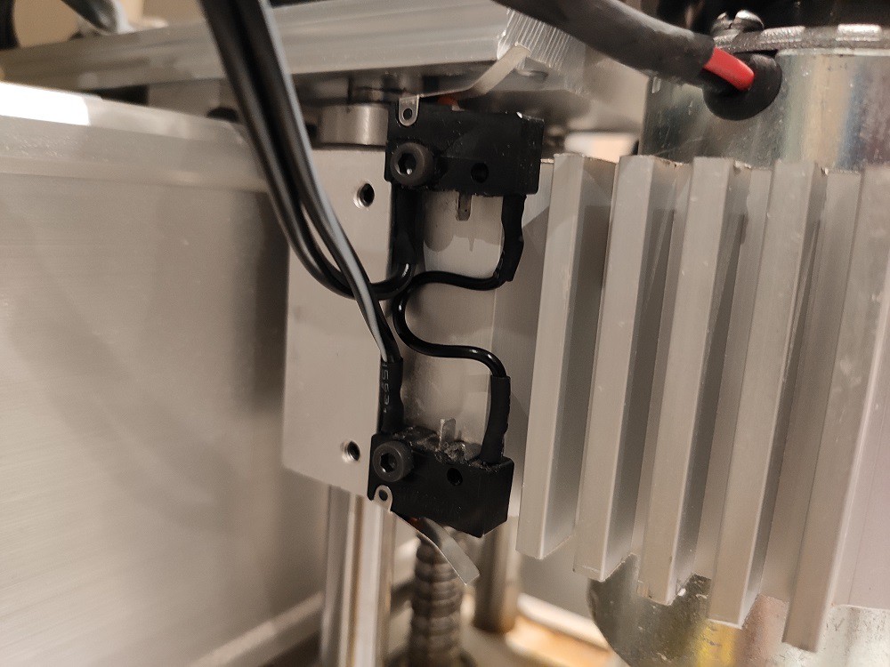
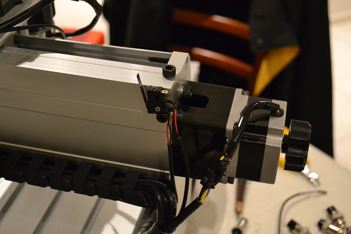
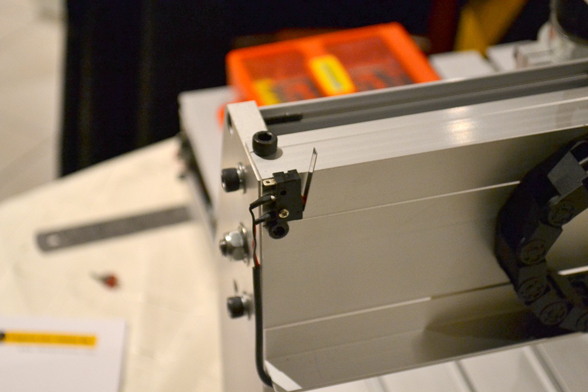
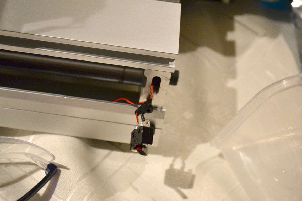
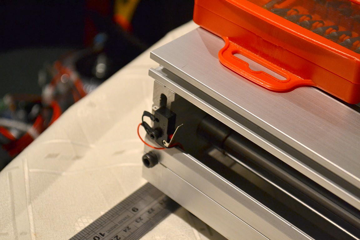
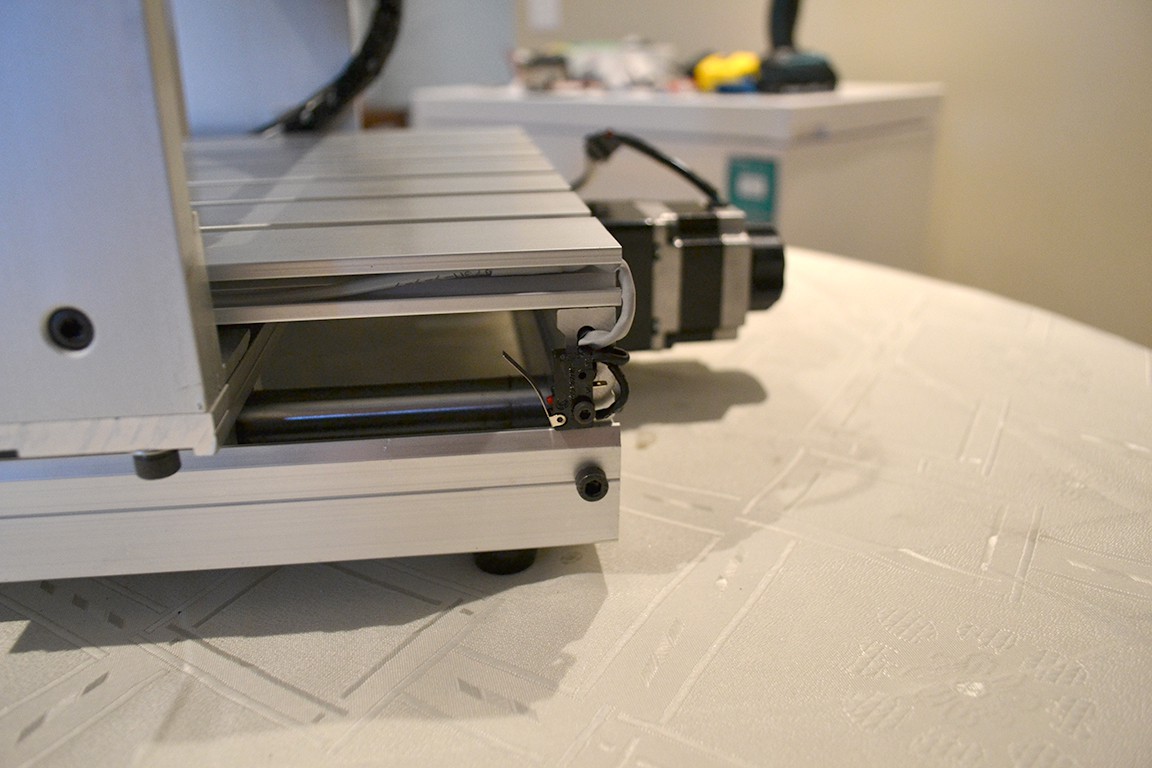
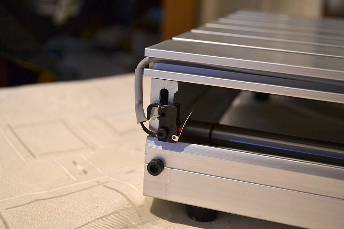
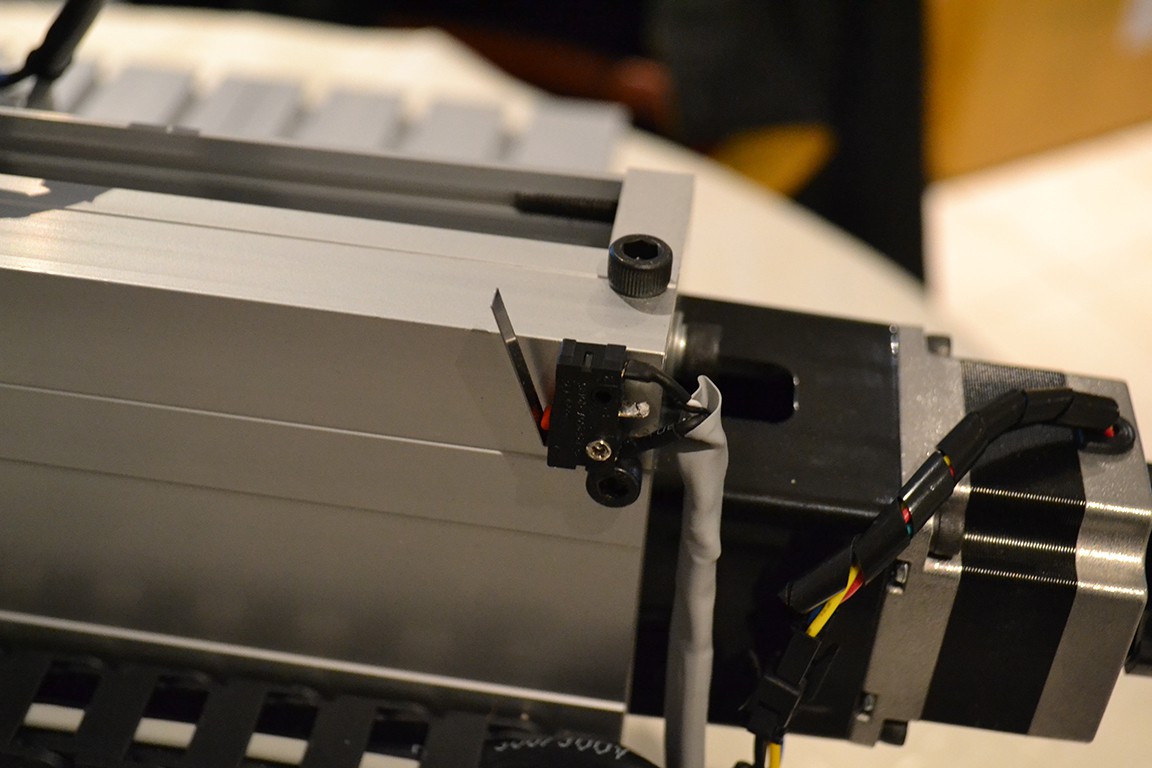
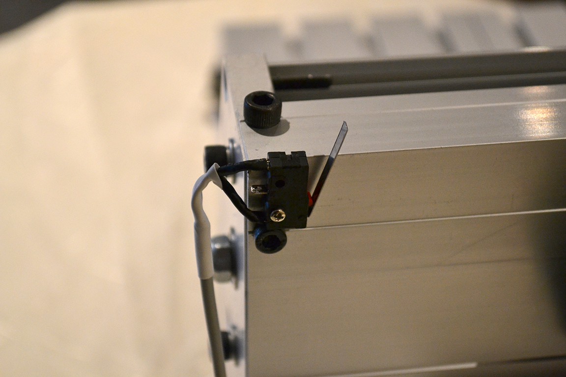
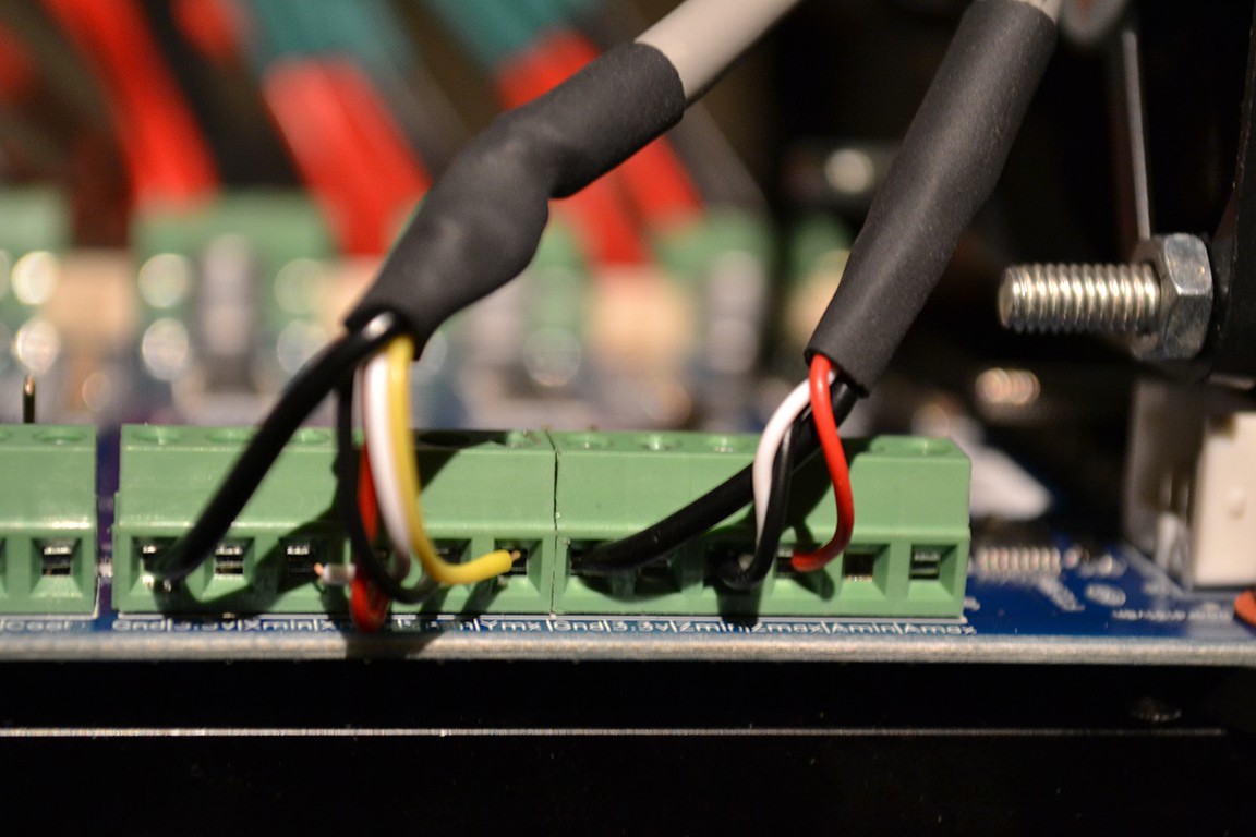
Another thing I upgraded on this machine was the existing limit switch wiring. The limit switches were Normally Open and setup in parallel. I changed it to Normally Closed and in series for better noise immunity, and fault detection.
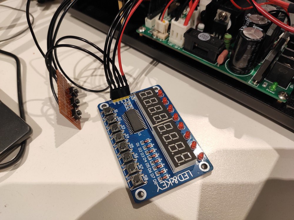
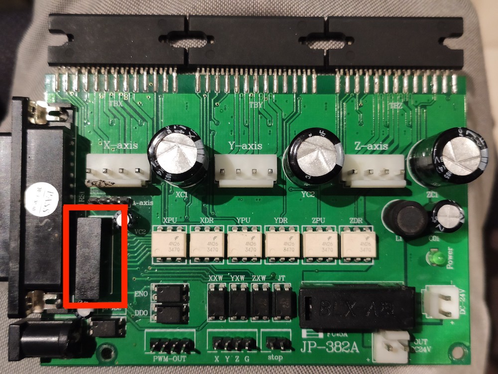
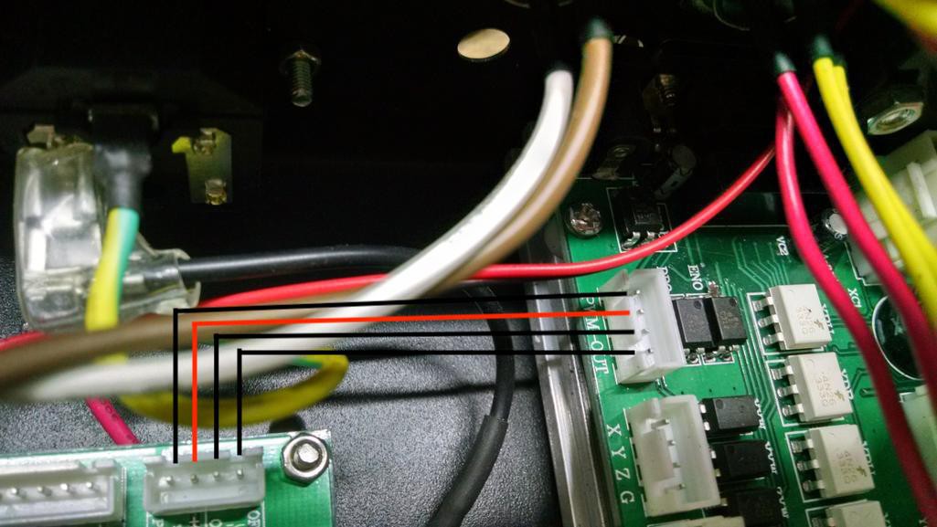
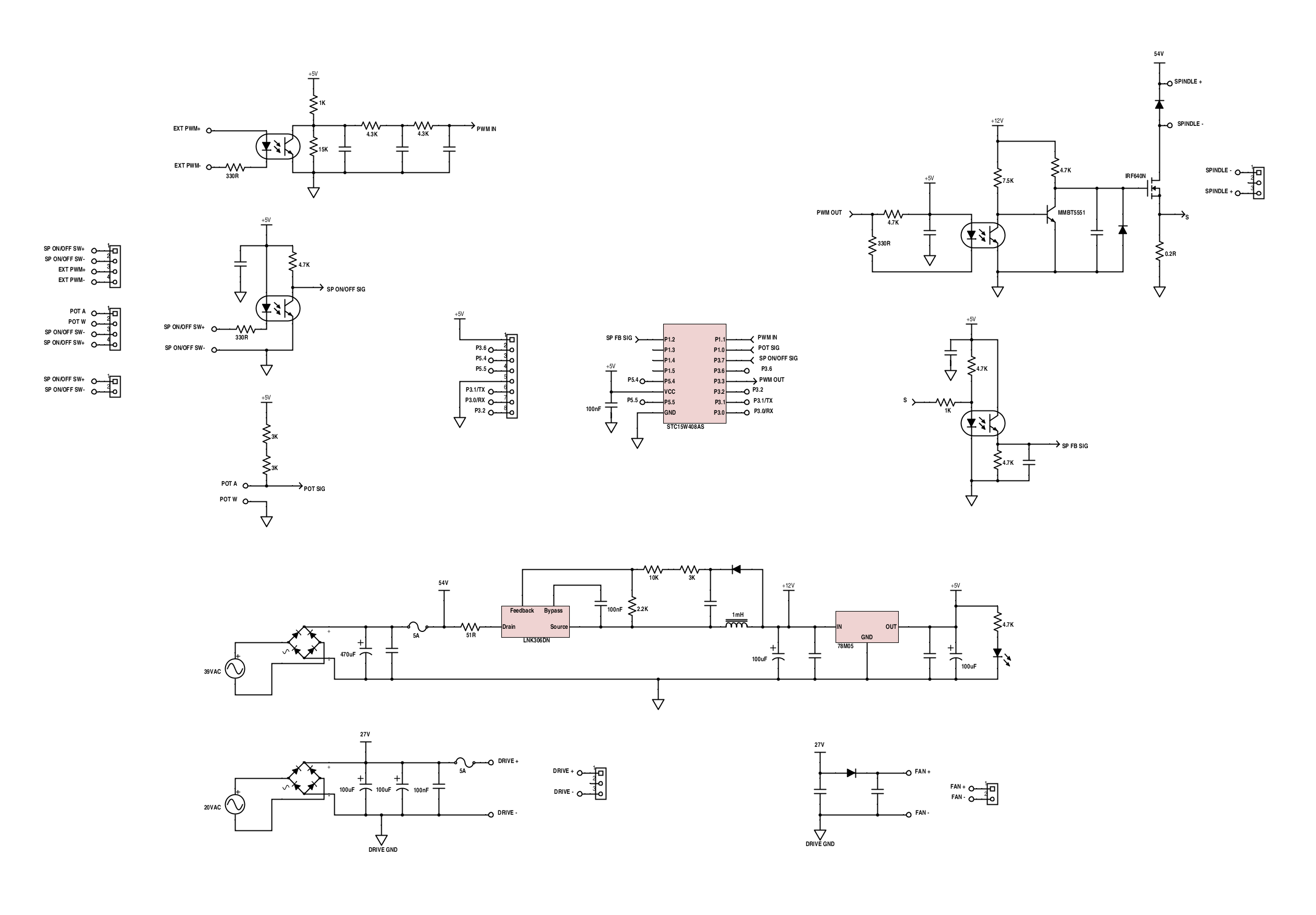
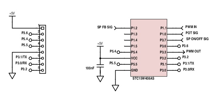
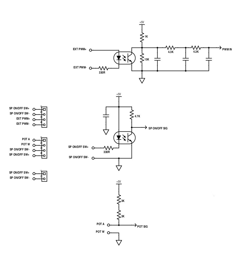
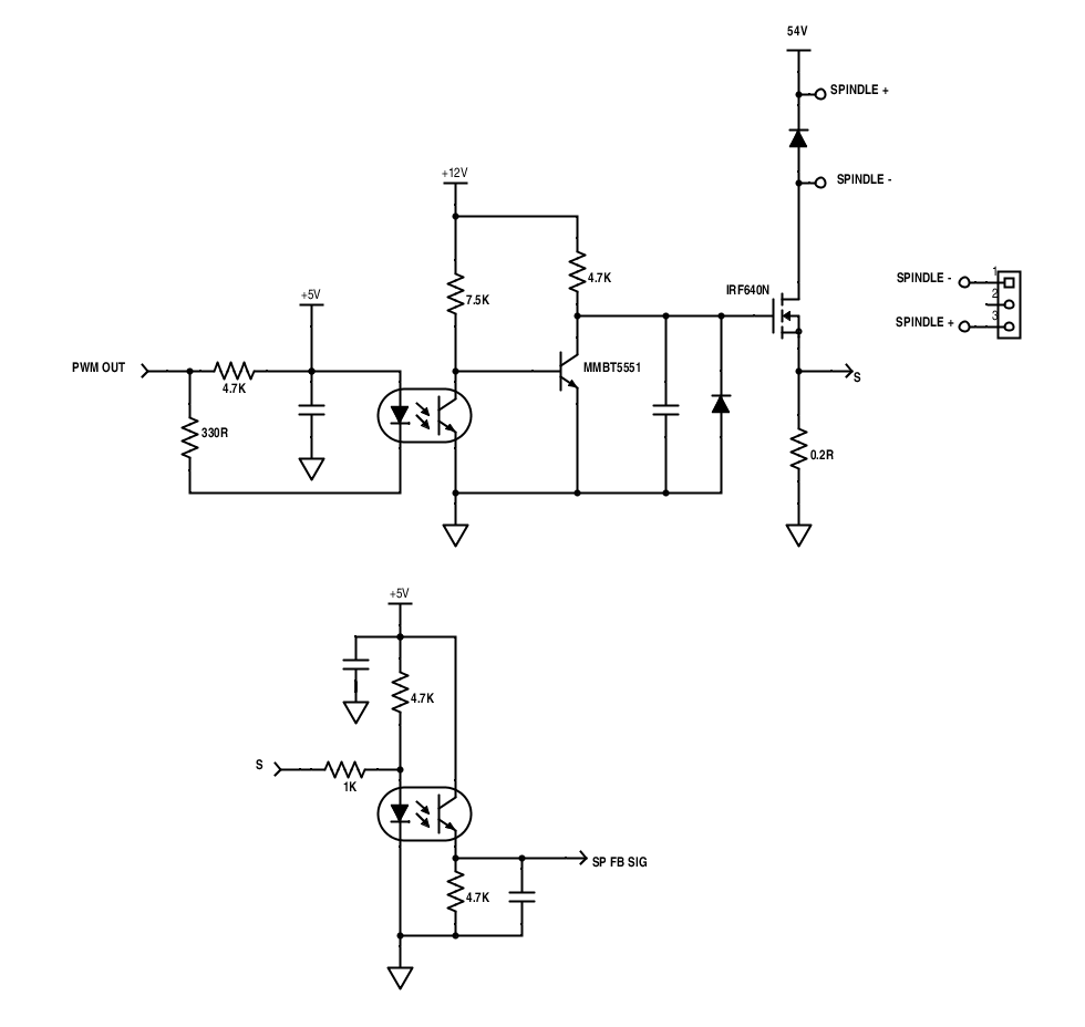
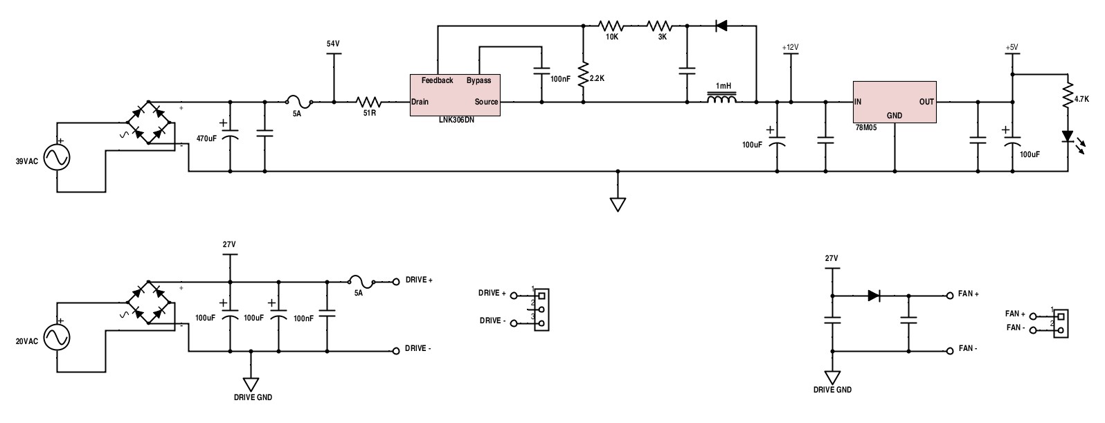
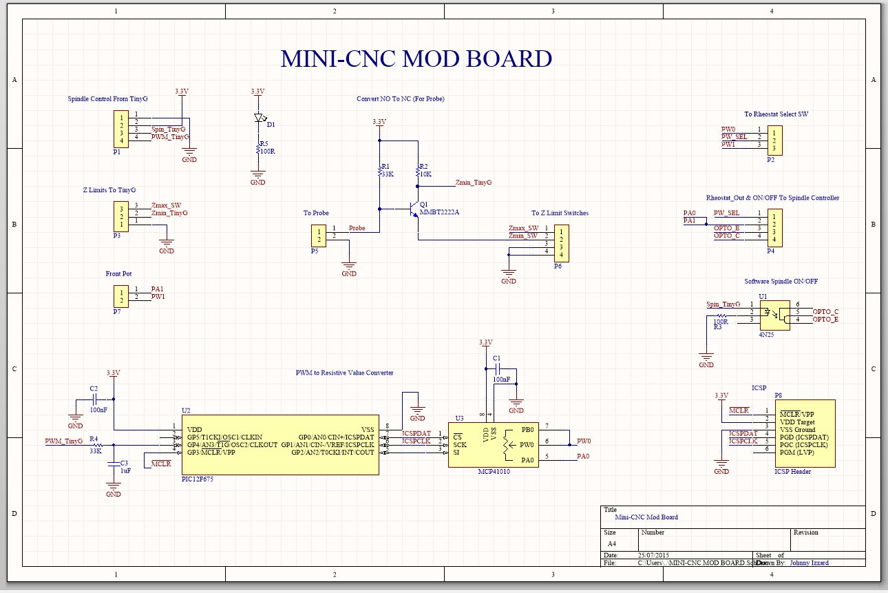
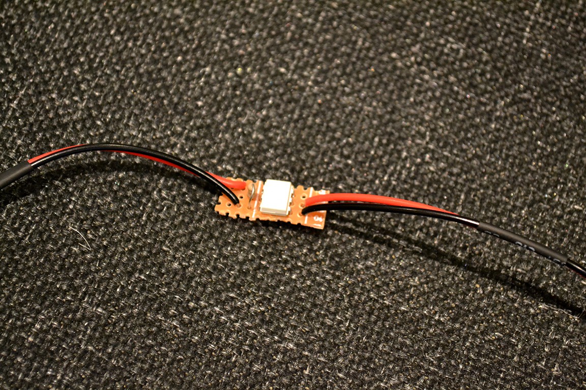
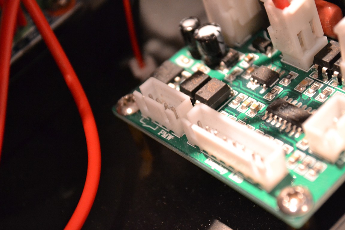
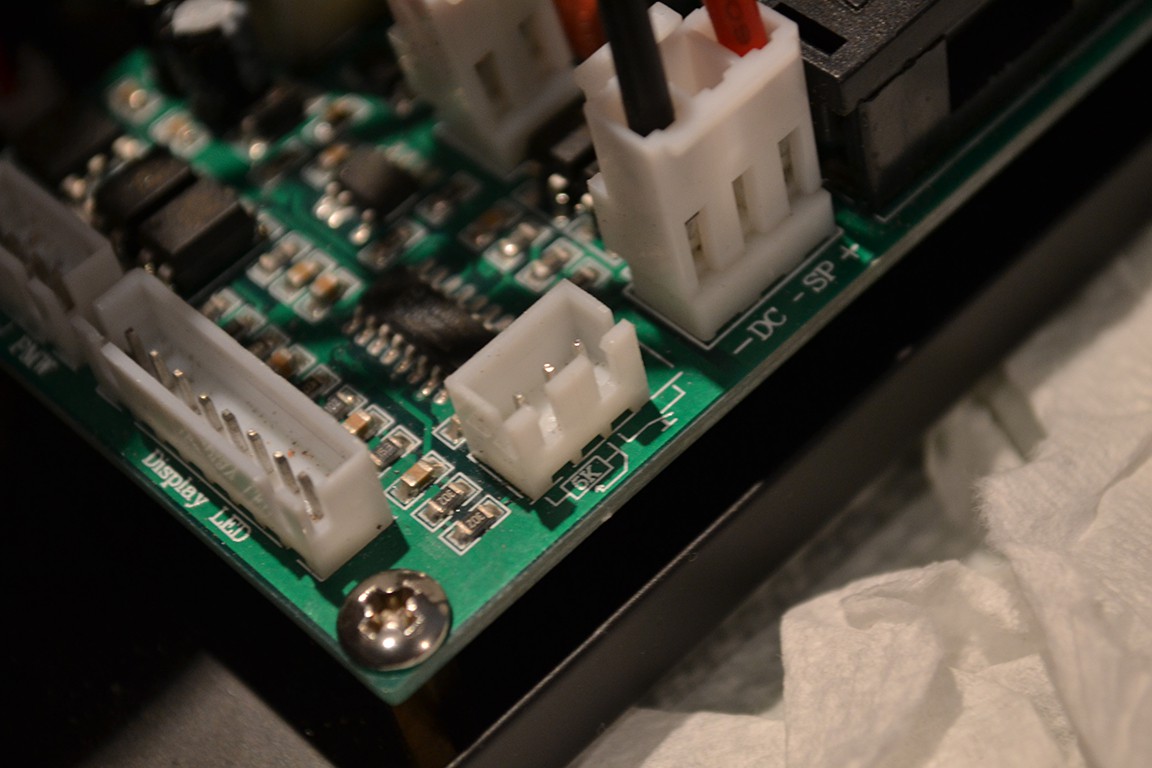
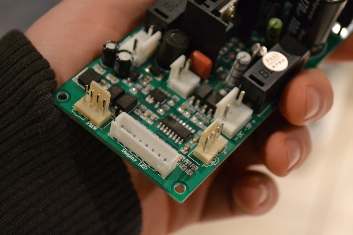
I have spindle ON/OFF and PWM control working in software.
Visit the project logs to see what I've done.
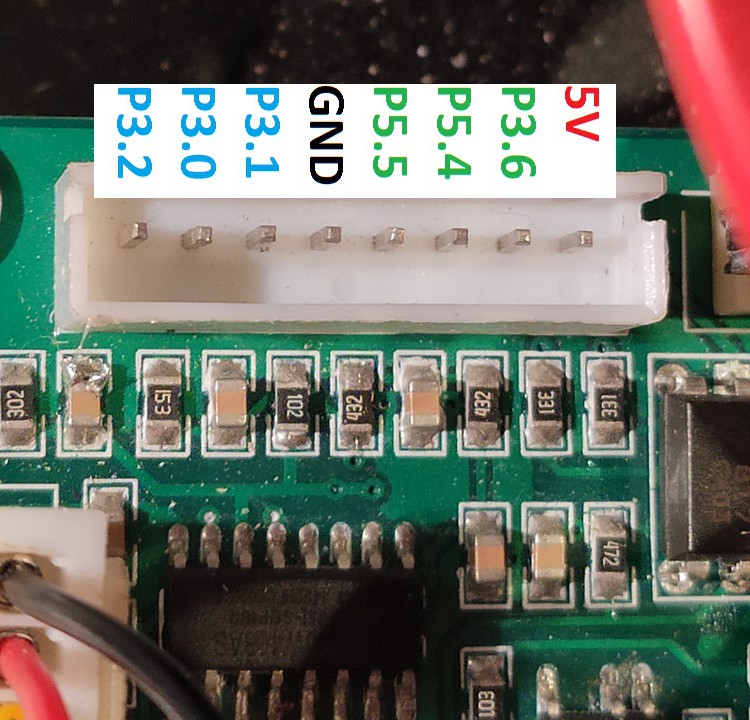
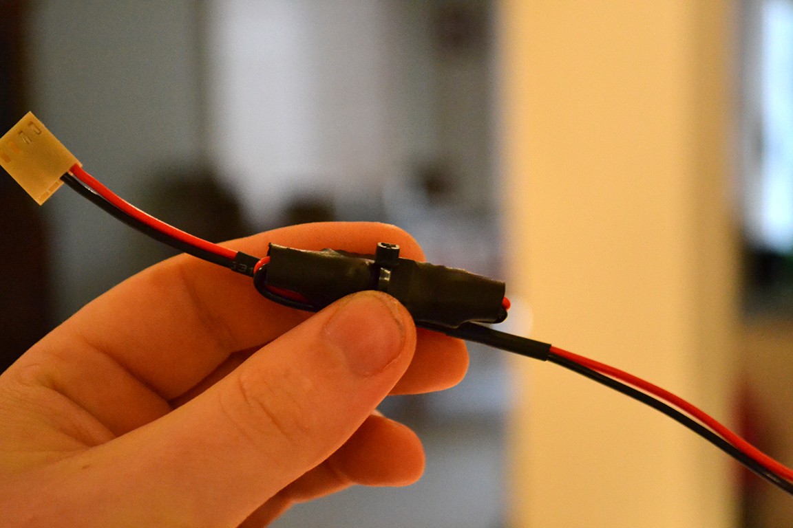
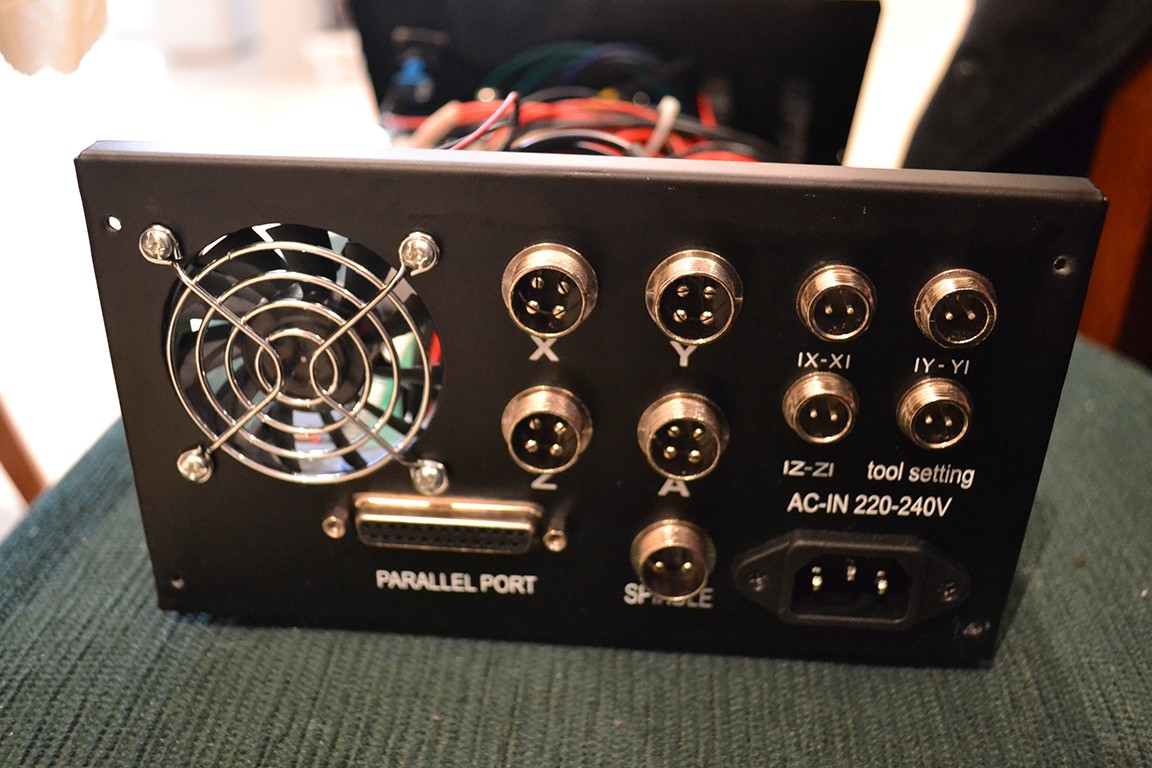
 I then discovered the ESP32 port of GRBL and wanted to try that, but didn't want to rewire everything again just to try out new controllers. So I put the original stepper controller back in and tested GRBL plugged in via the parallel port.
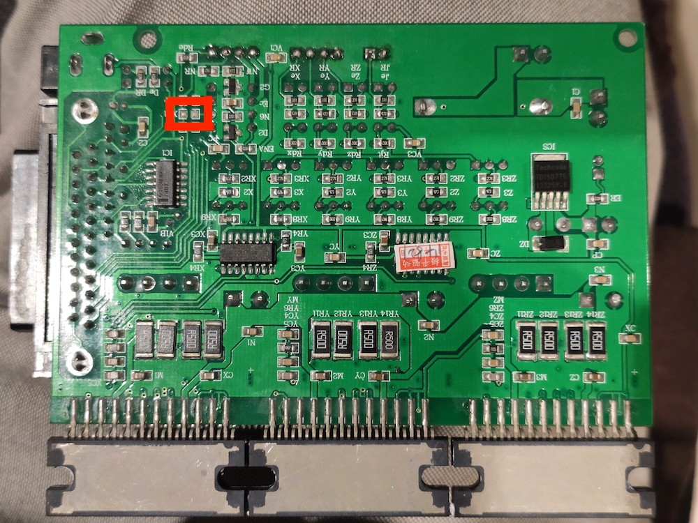
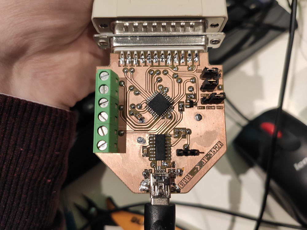
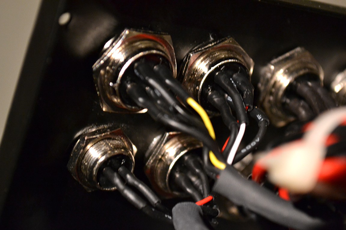
 (as seen from back of female connector)
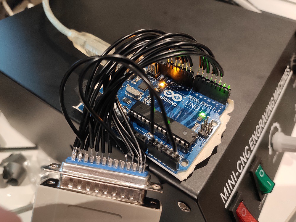


 danjovic
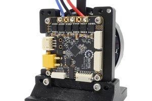
 Josh Pieper
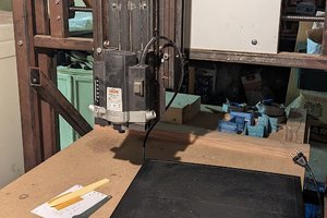
 JP Gleyzes
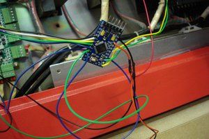
 msraynsford
Hi, I love your project! Your page helped me a lot understanding my CNC3040 machine which seems a bit newer than yours. My progress is documented here on HaD and in a (never-ending :D) YT series.
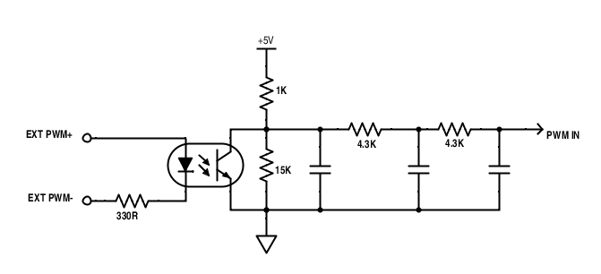
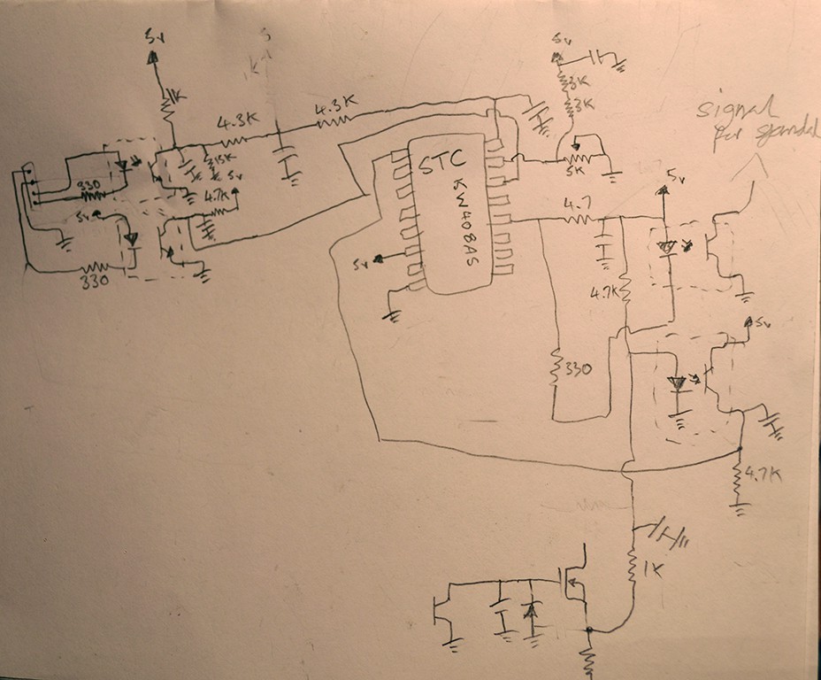
Your work on optimizing the speed settings shows me how badly designed these machines are, and how fiddly the speed adjustment is. I went another route, bypassed the optic coupling that drives the spindle mosfet and made my own PWM.
greetings, joekutz