 Johnny
So I never got round to getting software speed control working, just didn't need it and couldn't be bothered, manual control works fine for what I do...
Recently I started working on my Nixie Clock project again and I needed to mill a wooden enclosure. So I dusted off the CNC and had a go. The TinyG somehow changed its G54 during a big job, and ruined the work. This happened several times more. I looked on Synthetos's github for an update for the TinyG v8, but there hasn't been one for 4 years! Seems they only work on the TinyG G2 these days. So I decided it was time to let the TinyG go...
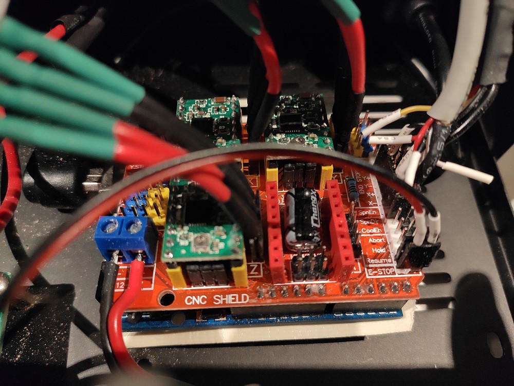
At work we use a X-Carve which runs on GRBL. I've never had an issue with GRBL, so I swapped out the TinyG for GRBL. I placed Arduino Uno with CNC Shield found on ebay. And was very pleased with the results.
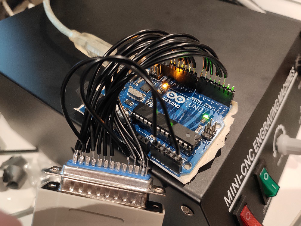
 I then discovered the ESP32 port of GRBL and wanted to try that, but didn't want to rewire everything again just to try out new controllers. So I put the original stepper controller back in and tested GRBL plugged in via the parallel port.
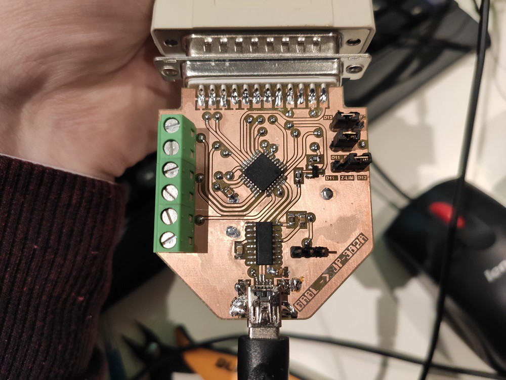
Some reverse engineering of the parallel port was required. Here's what I found:
 (as seen from back of female connector)
- PIN 1 - Spindle Enable
- PIN 2 - X Step
- PIN 3 - X Direction
- PIN 4 - Y Step
- PIN 5 - Y Direction
- PIN 6 - Z Step
- PIN 7 - Z Direction
- PIN 8 - A Step
- PIN 9 - A Direction
- PIN 10 - E-Stop
- PIN 11 - X Limit
- PIN 12 - Y Limit
- PIN 13 - Z Limit
- PIN 14 - Step Enable (all axis) (does nothing, see later log)
- PIN 15 - Probe
- PIN 16 - ?
- PIN 17 - Spindle PWM
- PIN 18-25 - Ground.
All are active low.
I needed to slightly modify GRBL's config.h:
Un-comment INVERT_SPINDLE_ENABLE_PIN and USE_SPINDLE_DIR_AS_ENABLE_PIN.
Note Spindle Dir pin is on D13 pin on arduino and this will toggle with the bootloader LED flashing at startup. This means your spindle will inadvertently turn on and off a few times if you are in dial mode with the dial left at full lol. To avoid this, remove the bootloader and download the grbl firmware straight to flash.
PWM signal needs to be inverted.
And settings currently are:
$0=10 (Step pulse time, microseconds)
$1=25 (Step idle delay, milliseconds)
$2=7 (Step pulse invert, mask)
$3=6 (Step direction invert, mask)
$4=0 (Invert step enable pin, boolean)
$5=1 (Invert limit pins, boolean)
$6=0 (Invert probe pin, boolean)
$10=1 (Status report options, mask)
$11=0.010 (Junction deviation, millimeters)
$12=0.002 (Arc tolerance, millimeters)
$13=0 (Report in inches, boolean)
$20=1 (Soft limits enable, boolean)
$21=0 (Hard limits enable, boolean)
$22=1 (Homing cycle enable, boolean)
$23=3 (Homing direction invert, mask)
$24=25.000 (Homing locate feed rate, mm/min)
$25=500.000 (Homing search seek rate, mm/min)
$26=250 (Homing switch debounce delay, milliseconds)
$27=2.000 (Homing switch pull-off distance, millimeters)
$30=11000 (Maximum spindle speed, RPM)
$31=0 (Minimum spindle speed, RPM)
$32=0 (Laser-mode enable, boolean)
$100=400.000 (X-axis travel resolution, step/mm)
$101=400.000 (Y-axis travel resolution, step/mm)
$102=400.000 (Z-axis travel resolution, step/mm)
$110=2000.000 (X-axis maximum rate, mm/min)
$111=2000.000 (Y-axis maximum rate, mm/min)
$112=700.000 (Z-axis maximum rate, mm/min)
$120=10.000 (X-axis acceleration, mm/sec^2)
$121=10.000 (Y-axis acceleration, mm/sec^2)
$122=10.000 (Z-axis acceleration, mm/sec^2)
$130=270.000 (X-axis maximum travel, millimeters)
$131=370.000 (Y-axis maximum travel, millimeters)
$132=50.000 (Z-axis maximum travel, millimeters)
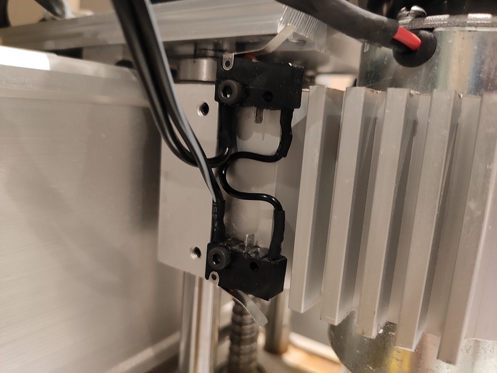
GRBL and the original stepper controller only has one limit switch input per axis, so I've had to rewire the limit switches in series (because I'm using NC switches).
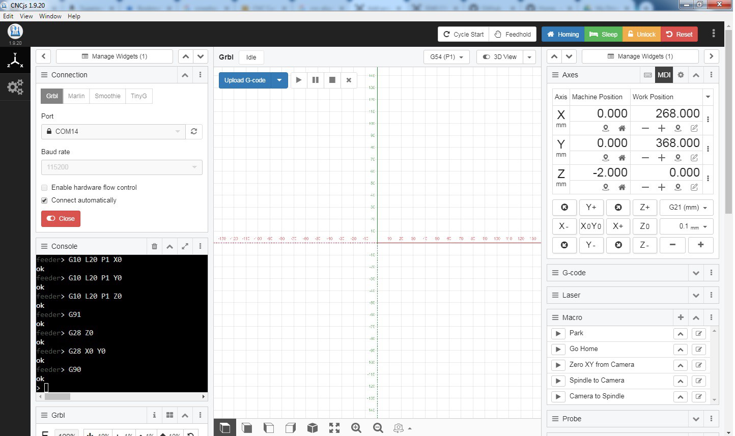
The G-Code sender I'm using is called CNCjs.
Discussions
Become a Hackaday.io Member
Create an account to leave a comment. Already have an account? Log In.