 Johnny
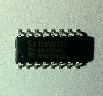
I've found the datasheet for the mysterious STC15W408AS microcontroller on the spindle controller board. Turns out it's a 8051 at heart. The datasheet is well documented and is surprisingly in well written english. The device is super easy to program too, only need a USB to UART adapter, Keil C51 compiler, uVision4, and a STC ISP application. Hopefully I can read the program memory and save it as a backup. This may be the neater solution. Just program the micro to have the PWM feature. I'll do more reverse engineering and have a play I think.
Discussions
Become a Hackaday.io Member
Create an account to leave a comment. Already have an account? Log In.
Hi Johnny, thanks a lot and even more for the reverse engineering on the JP4218 board! Thanks to you I could finally solve the problem of the Mach3 software-controlled spindle RPM setting. What I did is not complicated and maybe even already known by some people. I just short-circuited the first of the R in the low-pass PWM filter (only one is enough), disconnected the front pot resistor chain from where it was (pin POT SIG of the micro-controller) and connected it to the collector of the PWM opto-coupler. I also increased the last capacitor of the RC PWM filter to 10uF. Not to forget- I also connected PWM-IN and POT SIG of the STC microconroller and removed the 1K resistance between the collector of the PWM optocoupler and 5V. Now I can controll the RPM (it is still not linear, but...) from Mach3 and any Gcode program. Mach3 Configuration: Pin 17 (active: Low) is used for PWM and pin 1 is used for switching the spindle On/OFF (active: Low). The PWM is set at 300kHz and Minimum PWM is 0%. I even have a kinda of dual control: the front pot can override the PWM control when more RPM is needed.
Are you sure? yes | no
Well done! Sounds like a fairly simple solution. Don't even need to reprogram the micro. In the near future (when I get motivated to do more), I plan to make a programmer board that connects to the Display connector. The Display connector has TX, RX, 5V and GND, so just need a USB to UART ic and you can flash new firmware. I plan on writing firmware for it in the near future, just can't be bothered at the moment lol. Good part about that solution would be that no modifications to the PCB would be needed and it's fun writing code :P.
Are you sure? yes | no
Be nice to see your schematic.
Are you sure? yes | no
sure, how can I add a picture, I do not see any possibility for an attachment here...
P.S: I've sent it via a PM on this forum... Note that the front pot is to be used with care. I intend to calibrate the PWM-generated voltage at the POT SIG micro input (as far as I can do this), once I get an RPM meter from China and using your plots posted here, in this case, the pot would need be left in the min-RPM position (5k) in order not to disturb the calibration
Are you sure? yes | no
I used a L817 controlled by PWM signal, the output of the phototransistor is connected to a 10k resistor in parallel with an electrolytic capacitor 2 uF and then also the pins where there was the trimer 5k original.
The 10K resistor keeps the engine off, when the transistor goes into conduction the resistance decreases and the engine runs.
It is not linear but works with programmable speeds by Mach3.
This is the easiest and cheaper way to have speed control..
Are you sure? yes | no
I see. Nice work!
Are you sure? yes | no
Hello,
I have solved the problem of variable-speed spindle with a transistor driven by the pin 17 of the parallel port. The transistor varies the voltage on STC15W408AS's PWM-in pin.
I connected the tx and rx pin to serial PC with a CP2102 and it receives a stream of bytes. I beleave they are status information because when change speed ranges the stream change too. You know in what format the datas are sent on the serial ?
Are you sure? yes | no
Hey,
do you have a JP-1482 with the same version number? My spindle controller uses a opto-coupler to input the PWM signal and has a RC filter to convert it to an analog voltage for a ADC pin to read. So it's simple to test. I've put 5V 100% (just straight 5VDC) duty and nothing happens. I've put 50% at various frequencies and nothing happens. I tried by-passing the filter and that didn't work. Spent some time on it and concluded that the feature on my model has been removed at a software level. About the TX information, I have seen digital signals on the LCD connector, but can't remember seeing anything on the TX pin (it was a long time ago, I may check that again). I assume this is for a character display on a different model. What spindle controller model do you have? Check my pictures, does it look the same? Can you send a link with pictures?
Thanks for sharing your experience.
John.
Are you sure? yes | no
I have the same problem here. I've confirmed that a PWM into the board will generate a variable voltage on the p1.1 pin of the microcontroller, but the spindle never moves.
Are you sure? yes | no
Hi Johnny,
do you have news ??
I'll like to know what uP drop out by serial pins..
Are you sure? yes | no
Sorry I don't understand the question
Are you sure? yes | no